Berker 80141329 Bruksanvisning

Berker Växla 80141329

Läs gratis den bruksanvisning för Berker 80141329 (4 sidor) i kategorin Växla. Guiden har ansetts hjälpsam av 11 personer och har ett genomsnittsbetyg på 4.8 stjärnor baserat på 6 recensioner. Har du en fråga om Berker 80141329 eller vill du ställa frågor till andra användare av produkten? Ställ en fråga

Sida 1/4
z
}
01
Berker GmbH & Co. KG - Zum Gunterstal - 66440 Blieskastel, Germany
8016 17 xx, 8014 13 xx
KNX push-button 1gang with labelling
field and LED
8016 27 xx, 8014 23 xx
KNX push-button 2gang with labelling
field and LED
8016 37 xx, 8014 33 xx
KNX push-button 3gang with labelling
field and LED
8016 47 xx, 8014 43 xx
KNX push-button 4gang with labelling
field and LED
801x 1x xx
Push-button
6LE000455C
Systemlink start-up
The function of the device is software-de-
pendent. The software is to be taken from
the product database. You can find the latest
version of the product database, technical
descriptions as well as conversion and addi-
tional support programmes on our website.
Easylink start-up
The function of the device is configuration-de-
pendent. The configuration can also be done
using devices developed specially for simple
setting and start-up.
This type of configuration is only possible
with devices of the easylink system. Easylink
stands for easy, visually supported start-up.
Preconfigured standard functions are
assigned to the in/outputs by means of a ser-
vice module.
Correct use
Operation of consumers, e.g. light on/
o, dimming, blind up/down, saving and
opening light scenes, etc.
Installation on bus application unit,
flush-mounted
Product characteristics
Start-up and programming in S-mode
and E-mode
Push-button functions: switching/
dimming, blind control, value transmitter,
scene call-up, specification of the heating
operating mode, forced control, stepping
switch
Two status LEDs per push-button
Function and colour of the status LEDs
configurable for the device
A white operation LED
Operation
The functions of the buttons, their opera-
tion and the activation of the loads can be
adjusted individuallay for each device.
There are two operating modes:
Single-surface operation:
Switching lighting on/o or dimming
brighter/darker is carried out alternately
by repeated touching a button.
Two-surface operation:
Two adjacent buttons form a function
pair. For example, touching the left-hand
surface switches/dims lighting on/makes
it brighter, touching the right-hand surface
switches it o/makes it darker.
Operating a function or load
Loads, such as lighting, blinds, etc., are
operated using the touch surfaces, which are
dependent on the device programming.
Press a button.
The stored function is executed.
Safety instructions
Electrical equipment may only be installed
and assembled by a qualified electrician.
Always follow the relevant accident pre-
vention regulations of the country.
Failure to comply with these installation
instructions may result in damage to the
device, fire or other hazards.
When installing and laying cables, always
comply with the applicable regulations
and standards for SELV electrical circuits.
These instructions are an integral component
of the product and must be retained by the
end user.
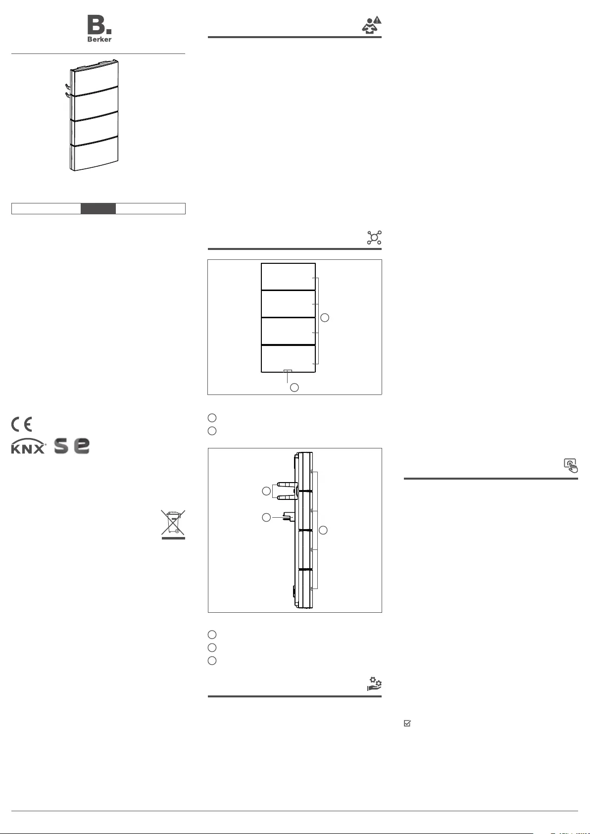
Design and layout of the
device
2
1
Figure 1: Front view of push-button 4gang
1
Operation LED
2
Buttons (number dependent on the variant)
3
5
4
Figure 2: Side view of push-button 4gang
3
Status LED
4
Fastening clamps
5
User interface (AST)
Function
System information
This device is a product of KNX system and
corresponds to the KNX guidelines. Detailed
specialised knowledge obtained from KNX
training courses is required for understand-
ing. The planning, installation and com-
missioning are carried out with the help of
KNX-certified software.
Correct Disposal of This product
(Waste Electrical & Electronic
Equipment).
(Applicable in the European Union and
other European countries with separate
collection systems).
This marking shown on the product or its
literature indicates that it hould not be dispo-
sed with other household wasted at the end
of its working life. To prevent possible harm
to the environment or human health from
uncontrolled waste disposal, please separate
this from other types of wastes and recycle it
responsibly to promote the sustainable reuse
of material resources.
Household users should contact either the
retailer where they purchased this product,
or their local government oce, for details
of where and how they can take this item for
environmentally safe recycling.
Business users should contact their supplier
and check the terms and conditions of the
purchase contract. This product should not
be mixed with other commercial wastes of
disposal.
02 T +49 541 760268-0 F +49 541 760268-199 info@hager.com hager.com – 10.2022
Troubleshooting
Bus operation is not possible.
Cause: Push-button does not match the pro-
grammed bus application unit. All status LEDs
are flashing red.
Replace push-button module or reprogram
bus application unit.
Accessories
Bus application unit, 8004 00 01
flush-mounted
Labeling field inlay Q.x 9498 xx xx
Warranty
We reserve the right to make technical and
formal changes to the product in the interest
of technical progress.
Our products are under guarantee within the
scope of the statutory provisions.
If you have a warranty claim, please contact
the point of sale or ship the device postage
free with a description of the fault to the
appropriate regional representative.
Information
The loading of non-compatible
application software is indicated by
red flashing of the status LEDs (3).
Mount push-button.
Easylink
Information
The device must be mounted on
the bus application unit for the E
mode start-up.
Information on the system configuration can
be taken from the extensive description of the
service moduleeasylink.
Appendix
Technical data
KNX Medium ................................................ TP 1
Start-up mode .......................systemlink, easylink
Rated voltage ................ s 21 … 32 V SELV KNX
Current consumption KNX ..................typ. 20 mA
Power consumption ......................... typ. 150 mW
Connection mode KNX .......... user interface (AST)
Degree of protection ...................................... IP20
Protection class ..................................................III
Operating temperature ..................... -5 … +45 °C
Storage/transport temperature ....... -20 … +70 °C
Information
The actuation pulse lasts for
the duration of the actuation.
Depending on the function, short
and long touches can trigger
dierent actions, e.g. switching/
dimming.
Information for electricians
Installation and electrical
connection
DANGER!
Touching live parts in the instal-
lation environment can result in
an electric shock.
An electric shock can be lethal!
Disconnect the connecting
cables before working on the
device and cover all live parts
in the area!
Connecting and installing the device
(figure 3)
The bus application unit is mounted and con-
nected to the KNX bus and installed in a wall
box.
Mount push-button (7) with design
frame (8) onto the bus application unit
(10) until the fastening clamps lock into
place, while doing so straightly insert
contact pins of the module into the
user interface (5).
Both devices are interconnected electri-
cally via the application interface AST.
Fix dismantling protection with screw
(11) if desired.
Mount push-buttons with labelling field
inlay (6) onto the push-button (7).
Dismantling
Loosen screw for dismantling protec-
tion (11).
Remove push-button from bus applica-
tion unit (10).
Start-up
Systemlink - Load application software
Since the application software is loaded
into the bus application unit, it is possible
to already load the application software and
assign the physical address of the bus appli-
cation unit together. If this has not taken place,
it is also possible to program later.
Load application software into the
device.
6
7
8
10
11
9
Figure 3: Assembly of the device
6
Push-button with labelling field inlay
7
Push-button
8
Frame (not within scope of delivery)
9
Illuminated programming button
10
Bus application unit, flush-mounted (not within scope of delivery)
11
Screw for dismantling protection
8016 17 xx, 8014 13 xx
1‘li KNX push-button LED özellikli ve etiketli
8016 27 xx, 8014 23 xx
2‘li KNX push-button LED özellikli ve etiketli
8016 37 xx, 8014 33 xx
3‘li KNX push-button LED özellikli ve etiketli
8016 47 xx, 8014 43 xx
4‘lü KNX push-button LED özellikli ve etiketli
801x 1x xx
Push-button
6LE000455C
z
}
03
Güvenlik uyarıları
Elektrikli cihazların takılması ve monte
edilmesi uygulamaları, sadece bir elektrik
uzmanı tarafından yapılabilir. Bu uygu-
lamalar sırasında bulunduğunuz ülkede
geçerli kazaları önleme yönetmelikleri dik-
kate alınmalıdır.
Kurulum talimatlarının dikkate alınma-
ması, cihazda hasarlara, yangına veya
başka tehlikelere yol açabilir.
Tesisat ve kablo hatlarını döşeme uygula-
malarında, SELV akım devreleri için geçerli
yönetmeliklere ve standartlara uyun.
Bu kılavuz, ürünün bir parçasıdır ve nihai
müşteri tarafından saklanmalıdır.
Cihazın yapısı
2
1
Resim 1: 4‘lü kontrol panelinin önden görünümü
1
Çalışma LED
2
Düğmeler (modele bağlı sayıdadır)
3
5
4
Resim 2: 4‘lü kontrol panelinin yandan görünümü
3
Durum LED‘i
4
Tespitleme mandalları
5
Kullanıcı arabirimi (AST)
Fonksiyon
Sistem bilgisi
Bu cihaz, KNX sisteminin bir ürünüdür ve
KNX direktiflerine uygundur. Ürünün iyice
tanınması için KNX eğitimleri ile verilen ayrıntılı
uzmanlık bilgileri bilinmelidir. Planlama, kuru-
lum ve işletime alma uygulamaları bir KNX
sertifikalı yazılım yardımıyla yapılır.
Systemlink‘in işletime alınması
Cihazın fonksiyonu yazılıma bağlıdır. İlgili yazı-
lım ürün veritabanında sunulmaktadır. Güncel
ürün veritabanı, teknik tanıtımlar ve de dönüş-
türme programları ve yardımcı programlar, her
zaman İnternet sayfamızda yayınlanmaktadır.
Easylink‘in işletime alınması
Cihazın fonksiyonu konfigürasyona bağlıdır.
Konfigürasyon, basit ayarların yapılması ve
işletime alma uygulamaları için özel olarak
geliştirilmiş cihazların yardımıyla da yapılabilir.
Bu tür bir konfigürasyon, sadeceeasylink sis-
temine sahip cihazlar ile yapılabilir.easylink,
görsel araçlarla desteklenen, basit işletime
alma uygulaması için kullanılır. Önceden kon-
figüre edilmiş standart fonksiyonlar, bir servis
modu yardımıyla giriş/çıkışlara atanmaktadır.
Talimatlara uygun kullanım
Elektrikli cihazlar kullanılır; örneğin ışık
AÇMA/KAPAMA, dimleme, jaluzi YUKARI/
AŞAĞI, ışık programları kaydetme ve
etkinleştirme vs.
Sıva altı veriyolu bağdaştırıcısına monte
edilir
Ürünün özellikleri
S ve E modunda işletime alınır ve prog-
ramlanır
Kontrol paneli fonksiyonları: Açma ve ka-
pama/dimleme, jaluzi kumandası, konum
sensörü, ışık programı açma, ısıtma ça-
lışma modu belirleme, zorunlu kumanda,
kademe şalteri ve karşılaştırıcı fonksiyonu
Her bir düğmede iki adet durum LED‘i
Cihazın çalıştığını gösteren durum
LED‘leri ve lambaların rengi ayarlanabilir
Beyaz çalışma LED‘i
Kullanım
Düğmelerin fonksiyonu ve kullanım şekli ve
de elektrikli cihazları kumanda etme şekli, her
bir cihaz için özel olarak ayarlanabilir.
İki farklı kullanım şekli söz konusudur:
Tek alanlı kullanım:
Örneğin bir aydınlatmayı açma/kapama
veya dimleme şeklinde aydınlatma sevi-
yesini yükseltme/azaltma, düğme alanına
tekrar tekrar basılarak yapılır.
İki alanlı kullanım:
Birbirine bitişik iki düğme alanı bir fonk-
siyon grubu oluşturur. Örneğin sol tarafa
basıldığında aydınlatma açılır/aydınlatma
seviyesi yükseltilir, sağ tarafa basıldığında
aydınlatma kapatılır/aydınlatma seviyesi
azaltılır.
Fonksiyonların veya elektrikli cihazların
kullanılması
Örneğin aydınlatma, jaluzi vs. gibi elektrikli
cihazlar, düğme alanlarına basılarak kullanılır
ve cihazın programlamasına bağlıdır.
Bir dokunma alanına basın.
Basılan düğme alanına atanmış fonksiyon
uygulanır.
Bu ürün nasıl bertaraf edilir?
(elektrikli ve elektronik ekipman
atıkları).
(Avrupa Birliği ülkelerinde ve seçmeli
toplama sistemlerini kullanan diğer Avrupa
ülkelerinde geçerlidir). Ürün veya doküman-
tasyonunda yer alan bu sembol, ürün ömrü-
nün sonunda diğer evsel atıklarla birlikte
bertaraf edilmemesi gerektiğini gösterir.
Kontrolsüz atık bertarafı çevreye veya insan
sağlığına zararlı olabilir, lütfen diğer atık türle-
rinden ayırın ve onu sorumlu bir şekilde geri
dönüştürün. Böylelikle maddi kaynakların
sürdürülebilir yeniden kullanımını teşvik ede-
ceksiniz. Bireyler, kendilerine ürünü satan
distribütörle iletişime geçmeye veya çevreye
saygılı bir şekilde geri dönüştürülebilmesi için
bu ürünü nerede ve nasıl elden çıkarabilecek-
lerini öğrenmek için belediyeye başvurmaya
davet edilir. Şirketler, tedarikçileriyle iletişime
geçmeye ve satış sözleşmelerinin şartlarını
incelemeye davet edilir. Bu ürün diğer ticari
atıklarla birlikte bertaraf edilmemelidir. Avrupa
ve İsviçre’nin her yerinde Kullanılabilir.


Produktspecifikationer

Varumärke: Berker
Kategori: Växla
Modell: 80141329
Bredd: 58.7 mm
Höjd: 58.7 mm
Material: Plast
Produktens färg: Vit
Antal per förpackning: 1 styck
Temperatur vid drift: -5 - 45 ° C
Temperaturintervall (förvaring): -20 - 70 ° C
Internationellt skydd (IP) kod: IP20
Brand kompatibilitet: Berker

Behöver du hjälp?

Om du behöver hjälp med Berker 80141329 ställ en fråga nedan och andra användare kommer att svara dig