Best ANKD Bruksanvisning


Läs gratis den bruksanvisning för Best ANKD (8 sidor) i kategorin ventilationskåpa. Guiden har ansetts hjälpsam av 5 personer och har ett genomsnittsbetyg på 4.7 stjärnor baserat på 3 recensioner. Har du en fråga om Best ANKD eller vill du ställa frågor till andra användare av produkten? Ställ en fråga

Sida 1/8
1
Model ANKDINSTALLATION INSTRUCTIONS
READ AND SAVE THESE INSTRUCTIONS
WARNING
TO REDUCE THE RISK OF FIRE, ELECTRIC SHOCK, OR
INJURY TO PERSONS, OBSERVE THE FOLLOWING:
1. Use this unit only in the manner intended by the
manufacturer. If you have questions, contact the
manufacturer at the address or telephone number in the
2. Installation work and electrical wiring must be done by a
qualified person(s) in accordance with all applicable codes
and standards, including fire-rated construction codes and
standards.
3. Sufficient air is needed for proper combustion and
exhausting of gases through the flue (chimney) of fuel
burning equipment to prevent backdrafting. Follow the
heating equipment manufacturer’s guideline and safety
standards such as those published by the National Fire
Protection Association (NFPA), and the American Society
for Heating, Refrigeration and Air Conditioning Engineers
(ASHRAE), and the local code authorities.
4. When cutting or drilling into wall or ceiling, do not damage
electrical wiring and other hidden utilities.
5. To reduce the risk of fire, use only metal ductwork.
!
INTENDED FOR DOMESTIC COOKING ONLY
!
!
CAUTION
1. For general ventilating use only. Do not use to exhaust
hazardous or explosive materials and vapors.
2. Clean filters and grease-laden surfaces frequently.
3. Do not repair or replace any part of this appliance unless
specifically recommended in this manual. All other servicing
should be done by a qualified technician.
4. Please read specification label on product for further
information and requirements.
CONTENTS
1 - Recirculation Box
1 - Recirculation Filter
1 - Decorative Grille
1 - Parts Bag (containing):
6 - #10 x .625” screws
4 - #8 x .375” screws
2 - #8 x 1” screws
PLAN THE INSTALLATION
1. Determine where recirculation box will exhaust through
cabinet.
Front (toe space), Back, Side (Left or Right).
14½” x 15” opening in cabinet base is required for
recirculation box.
3½” x 14¼” opening is required for exhaust.
2. Determine location of recirculation box.
Plan to align blower outlet with recirculation box inlet.
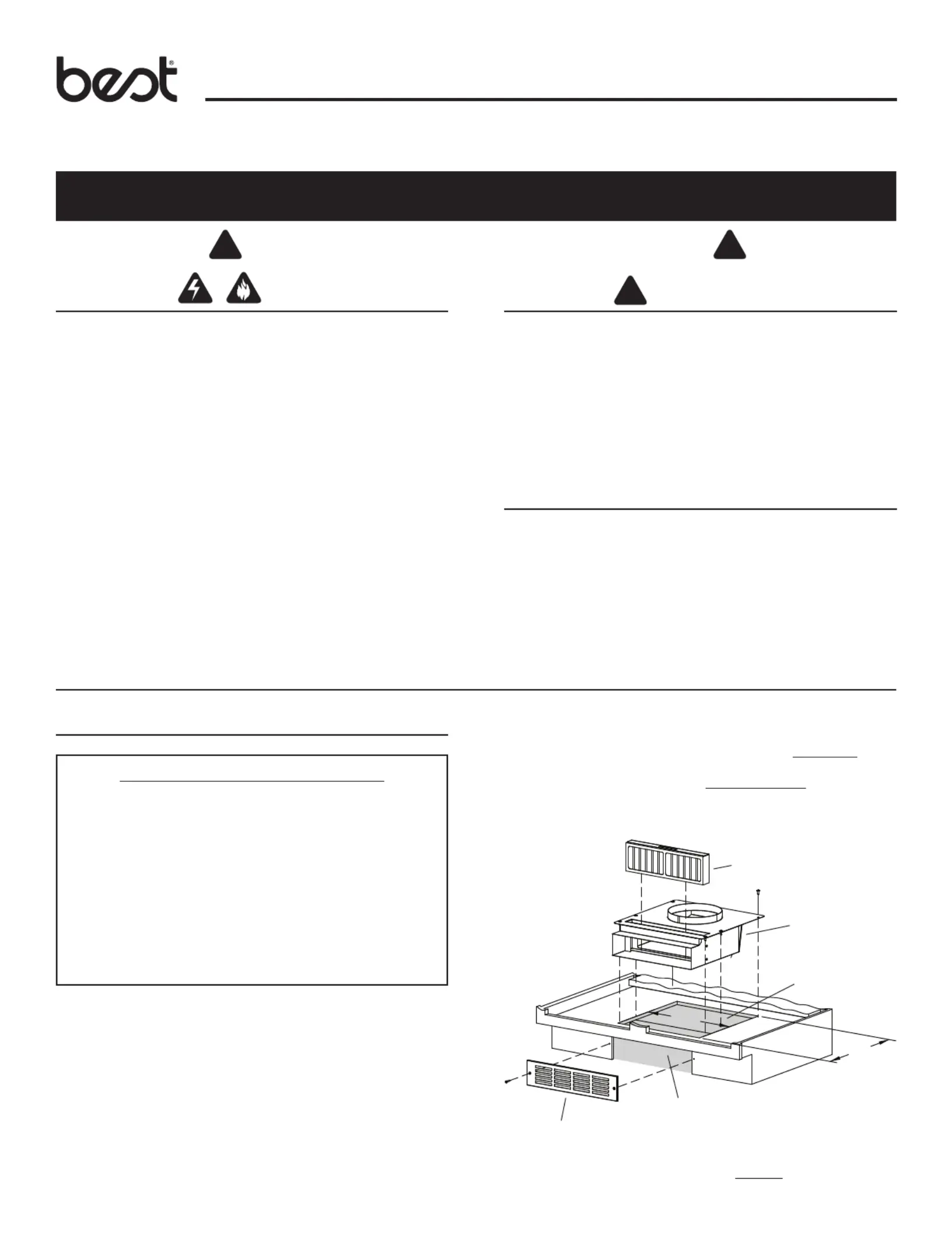
DOWNDRAFT RECIRCULATION KIT
15”
14½”
DECORATIVE
GRILLE
FILTER
RECIRCULATION
BOX
3½” x 14¼”
EXHAUST OPENING
OPENING IN
CABINET BASE
EXHAUST THROUGH CABINET FRONT (TOE SPACE)
IMPORTANT - Installation Requirements
The blower can be installed in either of two ways:
(1) attached to the downdraft and stabilized with
mounting legs.
(2) installed remotely (not attached to the downdraft),
using mounting brackets and wood framing.
Purchase blower separately. (Includes mounting legs and
mounting brackets.)
A minimum 24-inch wide cabinet is recommended.
The 8-inch round blower outlet and 8-inch round
recirculation box inlet must align vertically. (See page 2.)
3. Determine what lengths of duct are required. (Purchase
duct separately.)
A length of flexible or rigid 8” round duct is required to
connect blower exhaust to recirculation box inlet.
A length of 3¼” x 14” duct may be required to connect
to exhaust of recirculation box and extend to decorative
grille location.
2
Model ANKDINSTALLATION INSTRUCTIONS
INSTALL THE RECIRCULATION BOX
1. Cut opening in cabinet base.
Size: 14½” x 15”
Orientation depends upon direction of exhaust.
Double-check that blower outlet and recirculation box inlet will align.
2. Temporarily place recirculation box into opening in cabinet base.
Rotate back of box up slightly and insert exhaust end down into
opening.
Mark location of exhaust opening in toe space, rear, or side of
cabinet.
3. Remove recirculation box from opening.
4. Cut exhaust opening.
Size: 3½” x 14¼”
This opening will be covered with decorative grille.
5. Replace recirculation box into opening in cabinet base.
If necessary, attach a length 3¼” x 14” duct extension (not included)
to extend from recirculation box outlet to decorative grille location.
Seal the duct connection(s) with duct tape to make them secure and
air tight.
Use 6 - #10 x .625” screws to secure recirculation box to cabinet
base.
6. Install blower.
See blower instructions.
Use 8” round flexible or rigid duct to connect blower exhaust to
recirculation box inlet
Seal the duct connections with duct tape to make them secure and
air tight.
Drill 1/8” pilot holes through top of recirculation box and attach legs
to recirculation box with 4
- #8 x .375” screws.
7. Install decorative grille.
Use screws provided.
8. Remove polyfilm from filter.
Lift filter from slot.
Remove polyfilm.
Replace filter into slot.
CUSTOM-MADE DECORATIVE GRILLE
You can make your own decorative grille. Use the decorative
grille in this kit as a template for the overall size and mounting
hole locations. The grille opening pattern is up to you.
Equivalent area of grille slots for proper air flow = 18 in.
2
min.
15
14½”
EXHAUST
THROUGH
CABINET
SIDE
15”
14½”
FILTER REPLACEMENT
It is recommended that you replace the recirculation filter every
6 months. However, this may vary, depending upon the type
and amount of cooking you do. Call customer service or your
local distributor to order filter replacement Model AFCD.
ALIGN BLOWER
OUTLET WITH
RECIRCULATION
BOX INLET
METAL 8” ROUND
FLEXIBLE OR RIGID
DUCT (per local codes)
EXHAUST THROUGH
CABINET FRONT (TOE SPACE)
BLOWER
EXHAUST THROUGH
CABINET SIDE
EXHAUST THROUGH
CABINET BACK
Blower mounted
to downdraft using
mounting legs.
BLOWER
Blower mounted to
framing in remote
location - using
mounting brackets.
MOUNTING
LEGS
Blower outlet and
recirculation box
inlet must align.
(See below.)
OPTIONAL REMOTE BLOWER MOUNT
DIMENSIONS
EXHAUST
THROUGH
CABINET
BACK
3
Modèle ANKDGUIDE D’INSTALLATION
LIRE CES DIRECTIVES ET LES CONSERVER
AVERTISSEMENT
OBSERVEZ LES DIRECTIVES CI-DESSOUS AFIN
DE RÉDUIRE LES RISQUES D’INCENDIE, DE CHOC
ÉLECTRIQUE OU DE BLESSURES CORPORELLES :
1. Nutilisez cet appareil que de la manière prévue par le fabricant.
Si vous avez des questions, communiquez avec le fabricant à
ladresse ou au numéro de téléphone indiqués dans la garantie.
2. La pose de lappareil et les travaux délectrici doivent être
effectués par des personnes qualifiées conformément à la
réglementation en vigueur, notamment les normes de la
construction ayant trait à la protection contre les incendies.
3. Pour éviter les refoulements, lapport d’air doit être suffisant pour
brûler les gaz produits par les appareils à combustion et les
évacuer dans le conduit de fumée (cheminée). Respectez les
directives du fabricant de lappareil de chauffage et les normes
de sécuri, notamment celles publes par la National Fire
Protection Association (NFPA), lAmerican Society for Heating,
Refrigeration and Air Conditioning Engineers (ASHRAE) et les
codes des autorités locales.
4. Veillez à ne pas endommager le câblage électrique ou dautres
équipements non apparents lors de la découpe ou du perçage
du mur ou du plafond.
5. Pour réduire les risques d’incendie, utilisez seulement des
conduits en métal.
!
POUR USAGE DOMESTIQUE SEULEMENT
!
PLANIFICATION DE L’INSTALLATION
1. Déterminez l’emplacement de la sortie du boîtier de
recirculation au travers de l’armoire.
Avant (coup de pied), arrière, côté (gauche ou droit).
Une ouverture dans la base de l’armoire de
36,8 cm x 38,1 cm (14½ po x 15 po) est nécessaire pour
le boîtier de recirculation.
Une ouverture de 8,9 cm x 36,2 cm (3½ po x 14¼ po)
est nécessaire pour la sortie.
2. Déterminez l’emplacement du boîtier de recirculation.
Pvoyez aligner la sortie du ventilateur avec l’admission
du boîtier de recirculation.
ENSEMBLE DE RECIRCULATION POUR HOTTE ENCASTRÉE
SORTIE À LAVANT DE LARMOIRE (COUP DE PIED)
!
ATTENTION
1. Pour ventilation nérale uniquement. N’utilisez pas
cet appareil pour évacuer des matres ou des vapeurs
dangereuses ou explosives.
2. Nettoyez fréquemment les filtres et les surfaces graisseuses.
3. Ne réparez ou ne remplacez aucune pce de cet appareil à
moins que ce manuel le recommande précisément. Tout autre
travail de réparation doit être confié à un technicien qualifié.
4. Veuillez lire l’étiquette de spécifications du produit pour obtenir
plus de renseignements, notamment sur les exigences.
CONTENU
1 - Boîtier de recirculation
1 - Filtre de recirculation
1 - Grille décorative
1 - Sac de pièces (contenant) :
6 - Vis n° 10 x 0,625 po
4 - Vis n° 8 x 0,375 po
2 - Vis n° 8 x 1 po
38,1 cm
(15 po)
36,8 cm
(14½ po)
GRILLE
DÉCORATIVE
FILTRE
BOÎTIER DE
RECIRCULATION
SORTIE DE 8,9 CM X 36,2 CM
(3½ PO X 14¼ PO)
OUVERTURE
DANS LA BASE
DE LARMOIRE
3. Déterminez quelles longueurs de conduit sont requises.
(Conduits vendus séparément.)
Une longueur de conduit rond flexible ou rigide de
20,3 cm (8 po) est nécessaire pour raccorder la sortie du
ventilateur à l’admission du boîtier de recirculation.
Une longueur de conduit de 8,3 cm x 35,6 cm
(3¼ po x 14 po) peut être nécessaire pour raccorder
la sortie du boîtier de recirculation jusqu’à la grille
décorative d’évacuation.
IMPORTANT - Exigences d’installation
Il y a deux façons d’installer le ventilateur :
(1) fixé à la hotte encastrée et stabilisé par des pieds
de montage.
(2) instal à distance (et non rattaché à la hotte), à l’aide
de brides de montage et d’une charpente en poids.
Veuillez acheter le ventilateur séparément. (Comprend
les pieds et brides de montage.)
Une armoire d’au moins 61 cm (24 po) de largeur est
recommandée.
La sortie ronde de 20,3 cm (8 po) du ventilateur et
l’ouverture d’admission ronde 20,3 cm (8 po) du boîtier
de recirculation doivent être alignées verticalement.
(Voir page 4.)


Produktspecifikationer

Varumärke: Best
Kategori: ventilationskåpa
Modell: ANKD

Behöver du hjälp?

Om du behöver hjälp med Best ANKD ställ en fråga nedan och andra användare kommer att svara dig


ventilationskåpa Best Manualer

ventilationskåpa Manualer

Nyaste ventilationskåpa Manualer