Cosmo COS-36IRHP Bruksanvisning
Läs gratis den bruksanvisning för Cosmo COS-36IRHP (28 sidor) i kategorin Fläktkåpa. Guiden har ansetts hjälpsam av 28 personer och har ett genomsnittsbetyg på 4.3 stjärnor baserat på 8 recensioner. Har du en fråga om Cosmo COS-36IRHP eller vill du ställa frågor till andra användare av produkten? Ställ en fråga
Sida 1/28
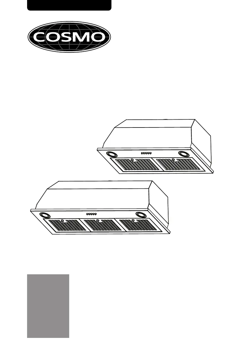
INSERT RANGE HOOD
COS-30IRHP
COS-36IRHP
IRHP RANGE HOOD SERIES
INSTALLATION INSTRUCTIONS
AND USE & CARE GUIDE
READ AND SAVE THESE INSTRUCTIONS.
FOR RESIDENTIAL USE ONLY.
PLEASE LEAVE THESE INSTRUCTIONS WITH THIS UNIT FOR
THE OWNER.
PLEASE RETAIN THESE INSTRUCTIONS FOR FUTURE
REFERENCE.
IMPORTANT:
INSTALLER:
OWNER:
Rev.23.03
Produktspecifikationer
| Varumärke: | Cosmo |
| Kategori: | Fläktkåpa |
| Modell: | COS-36IRHP |
Behöver du hjälp?
Om du behöver hjälp med Cosmo COS-36IRHP ställ en fråga nedan och andra användare kommer att svara dig
Fläktkåpa Cosmo Manualer

26 September 2024
26 September 2024
26 September 2024
26 September 2024
26 September 2024
26 September 2024
26 September 2024
26 September 2024
26 September 2024
26 September 2024
Fläktkåpa Manualer
Nyaste Fläktkåpa Manualer
9 April 2025
9 April 2025
9 April 2025
9 April 2025
9 April 2025
9 April 2025
9 April 2025
9 April 2025
9 April 2025
9 April 2025