Crestron CLTI-4HSW4 Bruksanvisning
Crestron
ej kategoriserat
CLTI-4HSW4
Läs gratis den bruksanvisning för Crestron CLTI-4HSW4 (4 sidor) i kategorin ej kategoriserat. Guiden har ansetts hjälpsam av 3 personer och har ett genomsnittsbetyg på 4.1 stjärnor baserat på 2 recensioner. Har du en fråga om Crestron CLTI-4HSW4 eller vill du ställa frågor till andra användare av produkten? Ställ en fråga
Sida 1/4

CLTI- & CLXI-4HSW4
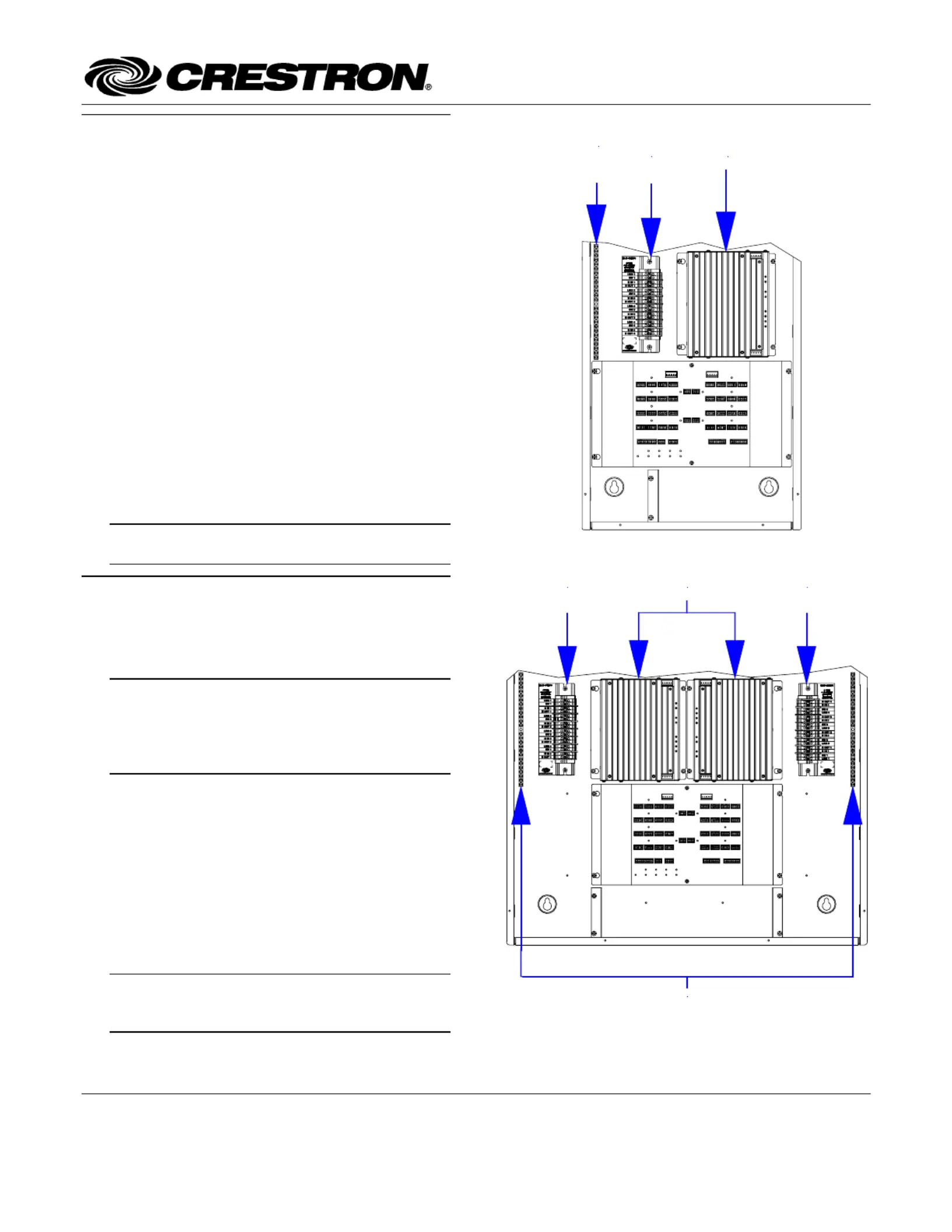
Terminal Block & Module Locations (Single-wide Enclosure)
Functional Summary
MODULETERMINAL
BLOCK
GROUNDING
TERMINAL
BLOCK
The Crestron
4-Feed, 4-High-Inrush Switch Terminal
Block and Module (CLTI-4HSW4 and CLXI-4HSW4,
respectively), are considered a single entity and must be
used together. They ship separately to permit termination
of the field wiring to the CLTI-4HSW4 prior to
installation of the CLXI-4HSW4, as described in this
guide. They can be mounted in any Crestron Automation
Enclosure (CAEN-Series Enclosures). The terminal block
is designed to terminate four circuit feeds (HOT and
NEUTRAL) and distribute the controlled circuits (LOAD)
to the fixtures. The module connects to the terminal block
and performs switching (non-dim) control of four
incandescent, low voltage, neon, cold cathode,
fluorescent, or HID lighting loads, or motor loads. The
maximum load is 8 amps (1 HP) for each controlled
circuit (32 amps total per module). The unit requires
230VAC 50 Hz input voltage. An oversize heat sink
dissipates heat efficiently. There are LEDs on the module
to indicate communication to a Cresnet
network, input
power to the module, and output power to the load.
NOTE: When connecting to an Arc Fault Breaker,
the load should not exceed 1000 watts.
Terminal Block & Module Locations (Double-wide Enclosure)
Installation
GROUNDING TERMINAL BLOCKS
MODULETERMINAL BLOCK
(LEFT)
TERMINAL BLOCK
(RIGHT)
Terminal block and module must be mounted into a
Crestron Automation Enclosure by a licensed electrician,
in accordance with all national and local codes.
CAUTION: This equipment is for indoor use only
and needs to be air-cooled. Mount in a well-
ventilated area. The ambient temperature must be
0°C to 40°C (32°F to 104°F). The relative humidity
must be 0% to 90% (non-condensing).
Terminal blocks are installed along the left side of single-
wide enclosures and along the outside edges (left and
right sides) of double-wide enclosures. Modules are
installed along the right side of single-wide enclosures
and side-by-side in the center of double-wide enclosures.
When installing modules and terminal blocks in a double-
wide enclosure, be sure to invert units on the right side so
that they can be properly wired. Refer to the illustrations
shown in the next column when considering the location
of terminal blocks and modules within an enclosure.
NOTE: Modules and terminal blocks must be
installed into the lowest available spaces and
continue toward the top of the enclosure.
Crestron Electronics, Inc. Installation Guide – DOC. 6412
15 Volvo Drive Rockleigh, NJ 07647 (2013808)
Tel: 888.CRESTRON 11.05
Fax: 201.767.7576 Specifications subject to
www.crestron.com change without notice.

Terminal Block & Module Crestron CLTI- & CLXI-4HSW4
Terminal Block Installation and Field
Wiring
Wiring Diagram of the Terminal Block to the Feed and
Load(s) (Single-wide and Left Side Double-wide Enclosures)
TO
LOAD
4
TO
LOAD
3
TO
LOAD
2
TO
LOAD
1
HOT 1 (*)
HOT 2 (*)
HOT 3 (*)
HOT 4 (*)
NEUTRAL
NEUTRAL
NEUTRAL
NEUTRAL
GRO UN D ING
TERMINAL
BLOCK
GN D
TERMINAL
BLOCK
LEFT
SIDE
WIRING
LABEL
AREA FOR
MODULE
LOCATION
LABEL
BYPASS
JUMPERS
(*) FROM 10 OR 16 AMP
CIRCUIT BREAKER
1. Use the two supplied self-tapping pan Phillips
screws (8B x ¼-inch (6 mm) length) to secure
the terminal block and the appropriate (left or
right) wiring label to the Crestron Automation
Enclosure. The wiring label lies beneath the
terminal block as shown in the two wiring
diagrams on this page.
NOTE: Both left and right wiring labels are
provided. The left-side labels are common for both
single and double-wide enclosures. The right-side
labels are only used in double-wide enclosures since
the modules and terminal blocks along the right side
must be inverted when mounting.
CAUTION: On this terminal block there are four
distinct circuits. Bypass jumpers are installed on the
on the brown and red sections of each circuit on the
terminal block to allow testing of the circuits and to
protect the module during installation. When properly
secured by two screws, each bypass jumper on a
circuit shorts the hot to switch so that the circuit is
receiving power. Do not remove any bypass jumpers
until all feed and load wiring has been completed, the
circuit has been tested for electrical faults, and the
module has been installed. Refer to “Module
Installation” on the next page. Jumpers are also
installed on the blue sections of the terminal block
and tie the neutrals together. These jumpers should
never be removed.
Wiring Diagram of the Terminal Block to the Feed and
Load(s) (Right Side Double-wide Enclosures)
TO
LOAD
1
TO
LOAD
2
TO
LOAD
3
TO
LOAD
4
HOT 1 (*)
HOT 2 (*)
HOT 3 (*)
HOT 4 (*)
NEUTRAL
NEUTRAL
NEUTRAL
NEUTRAL
GROUNDING
TERMINAL
BLOCK
GND
TERMINAL
BLOCK
RIGHT
SIDE
WIRING
LABEL
AREA FOR
MODULE
LOCATION
LABEL
BYPASS
JUMPERS
(*) FROM 10 OR 16 AMP
CIRCUIT BREAKER
NOTE: Use copper conductors only – rated 75°C
2. With the circuit breaker turned off, connect the
circuit feed (HOT and NEUTRAL) and
controlled circuit (LOAD) wires to the terminal
block per the markings provided on the wiring
label (as shown in the diagrams on this page).
Terminal blocks accept one 2.5 - 6.0 mm
2
wire.
Wires should be stripped to 12 mm. Tighten
terminal blocks to 1 Nm. Do not over tighten.
3. Grounding terminal blocks are available in the
cabinet for termination of ground wires. Tighten
to 4 Nm (2.5 - 6.0 mm
2
), 4.5 Nm (10.0 mm
2
), or
5.1 Nm (16 - 25 mm
2
).
4. Test the circuit for electrical faults by turning on
the circuit breaker and checking that the breaker
does not trip and that power is delivered to the
loads.
2 •
•
•
•• Terminal Block & Module: CLTI- & CLXI-4HSW4 Installation Guide – DOC. 6412

Crestron CLTI- & CLXI-4HSW4 Terminal Block & Module
Module Installation
NOTE: Before the two-position bypass jumpers,
shown in the illustration, are removed, the Crestron
Professional Automation Computer (PAC2), which
provides control to the system, should be properly
connected and contain a valid program to provide
control of the module.
CAUTION: Module contains electrostatic sensitive
devices (ESDs); unit must be handled from metal
chassis – do not touch PC board or components.
NOTE: Modules are to be installed after enclosure
has been completely wired. Refer to the terminal
block installation procedure on page 2 for details.
Wiring Diagram of the Terminal Block to the Module
(Single-wide and Left Side Double-wide Enclosures)
JUMPERS
INSTALLED
RE D
BRO W N
BLUE
RE D
BRO W N
BLUE
RE D
BR O W N
BLUE
RE D
BR O W N
BL U E
BL U E
BLUE
BLUE
BL U E
BYPASS JUMPERS ON BROWN AND
RED SECTIONS OF TERMINAL
BLOCK HAVE BEEN REMOVED
AFTER LOOSENING ALL SCREWS.
JUMPER ON BLUE SECTIONS
ARE NOT REMOVED.
ENLARGEMENT DETAIL:
BYPASS JUMPERS
RE M OVE D
1. Use the four supplied self-tapping pan Phillips
screws (8B x ¼-inch (6 mm) length) to secure
the module to the enclosure.
2. As shown in the wiring diagrams (next column),
connect the wires from the module to the
terminal block. Each wire exits the module
directly in line with, and is the same color as, the
terminal to which it should be connected. Wires
are pre-stripped to 12 mm. Tighten to 1 Nm. Do
not over tighten.
3. If the module is being installed above another
module within the enclosure, attach the supplied
module interconnect cable between the two
modules. The illustration below depicts the area
within a double-wide enclosure where the
corners of four modules meet.
NOTE: One wire on the module interconnect cable
may be a different color from the rest. The color has
no bearing on its orientation during installation.
Wiring Diagram of the Terminal Block to the Module
(Right Side Double-wide Enclosures)
Use Module Interconnect Cable to Wire Module to Module
MODULE
INTERCONNECT
CABLE ATTACHED
CONNECTION
NOT
MADE
JUMPERS
INSTALLED
RE D
BRO W N
BL U E
RE D
BRO W N
BL U E
RE D
BRO W N
BLUE
RE D
BRO W N
BLUE
BL U E
BLUE
BL U E
BLUE
BYPASS JUMPERS
REMOVED
BYPASS JUMPERS ON BROWN
AND RED SECTIONS OF TERMINAL
BLOCK HAVE BEEN REMOVED
AFTER LOOSENING ALL SCREWS.
JUMPER ON BLUE SECTIONS
ARE NOT REMOVED.
ENLARGEMENT DETAIL:
4. Turn on the circuit breaker and verify that the
green PWR LED on the module lights, the
breaker does not trip, and power is delivered to
the loads.
5. Turn off the circuit breaker and remove the two-
position bypass jumpers on the brown and red
sections of the terminal block. The jumpers on
the blue sections of the terminal block remain
installed. Refer to the figures in the next column
for a close-up of the jumpers.
Installation Guide – DOC. 6412 Terminal Block & Module: CLT- & CLX-4HSW4 •
•
•
•• 3
Produktspecifikationer
Varumärke: | Crestron |
Kategori: | ej kategoriserat |
Modell: | CLTI-4HSW4 |
Behöver du hjälp?
Om du behöver hjälp med Crestron CLTI-4HSW4 ställ en fråga nedan och andra användare kommer att svara dig
ej kategoriserat Crestron Manualer
30 Juli 2025
30 Juli 2025
30 Juli 2025
30 Juli 2025
30 Juli 2025
30 Juli 2025
30 Juli 2025
30 Juli 2025
30 Juli 2025
30 Juli 2025
ej kategoriserat Manualer
- I-Tec
- Baofeng
- Lecork
- Hager
- Oase
- Party Light & Sound
- Intellinet
- Scosche
- Neewer
- Thule
- Simagic
- Rane
- Jackery
- Monitor Audio
- Gloria
Nyaste ej kategoriserat Manualer
30 Juli 2025
30 Juli 2025
30 Juli 2025
30 Juli 2025
30 Juli 2025
30 Juli 2025
30 Juli 2025
30 Juli 2025
30 Juli 2025
30 Juli 2025