Dometic Comfort Control Center 2 Bruksanvisning
Dometic
Luftkonditionering
Comfort Control Center 2
Läs gratis den bruksanvisning för Dometic Comfort Control Center 2 (20 sidor) i kategorin Luftkonditionering. Guiden har ansetts hjälpsam av 6 personer och har ett genomsnittsbetyg på 4.2 stjärnor baserat på 3.5 recensioner. Har du en fråga om Dometic Comfort Control Center 2 eller vill du ställa frågor till andra användare av produkten? Ställ en fråga
Sida 1/20

USA
SERVICE OFFICE
Dometic Corporation
1120 North Main Street
Elkhart, IN 46514
CANADA
Dometic Corporation
46 Zatonski, Unit 3
Brantford, ON N3T 5L8
CANADA
For Service Center &
Dealer Locations
Please Visit:
www.eDometic.com
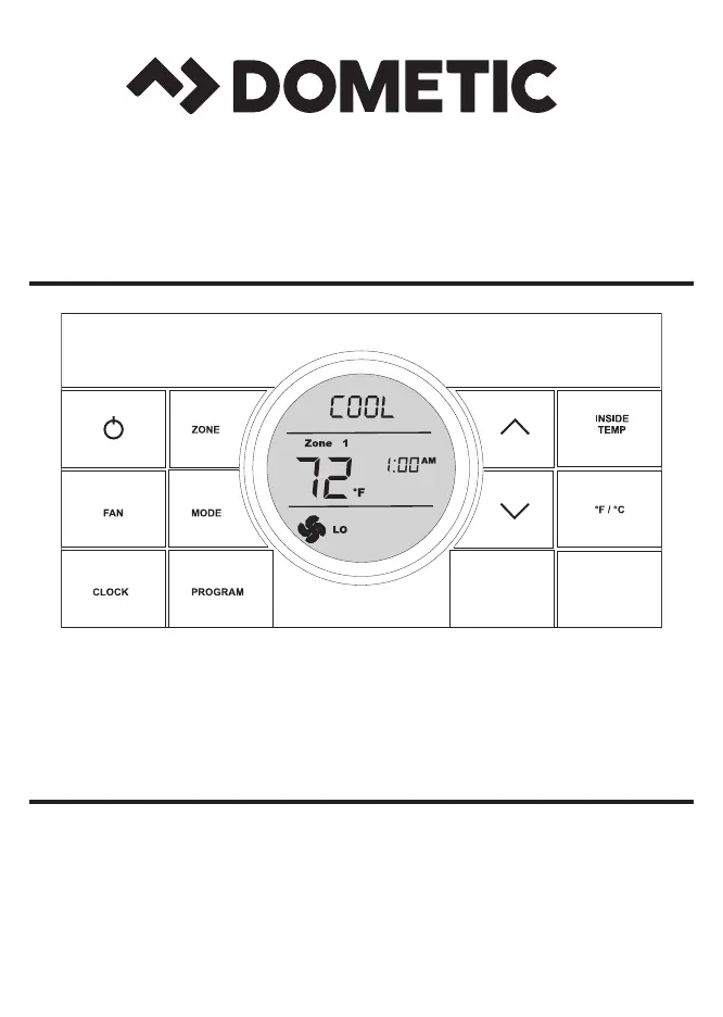
COMFORT CONTROL CENTER 2 THERMOSTAT
OPERATING INSTRUCTIONS
REVISION B
Form No. 3314149.018 08/16
(French 3314169.016_B)
©2016 Dometic Corporation
LaGrange, IN 46761
PROGRAMMABLE THERMOSTAT
MODEL
3314080.000 BLACK
3314080.015 WHITE

2
TABLE OF CONTENTS
INTRODUCTION ........................................................................................................................................... 2
DOCUMENT SYMBOLS ...............................................................................................................................3
ABOUT YOUR NEW THERMOSTAT ............................................................................................................3
A. Features ....................................................................................................................................3
B. SystemConguration&Initialization ......................................................................................... 3
C. QuickReferenceToControlButtons .........................................................................................5
D. Quick Reference To LCD Icons .................................................................................................5
PROGRAMMING&OPERATIONS ............................................................................................................... 6
A. ON/OFF ..................................................................................................................................... 6
B. ClockSetting .............................................................................................................................6
C. Temperature Format °F / °C ......................................................................................................7
D. Inside Temperature .................................................................................................................... 7
E. ZoneSelection ...........................................................................................................................8
F. ModeSelection .......................................................................................................................... 8
G. Fan Speed ................................................................................................................................. 9
H. Temperature Set-Point ...............................................................................................................9
MODE DESCRIPTION ................................................................................................................................10
A. “OFF” - Off Mode .....................................................................................................................10
B. “COOL”-CoolMode ...............................................................................................................10
C. “HP” - Heat Pump Mode .......................................................................................................... 10
D. “HS” - Heat Strip Mode ............................................................................................................ 11
E. “FAN” - Fan Mode .................................................................................................................... 11
F. “FURN” / “AQUA” - Furnace Or Aqua (Hydronic) Heating Mode ............................................. 11
G. “AUTO” - Auto Change Over Mode .........................................................................................12
SPECIAL FEATURES..................................................................................................................................12
A. Auto Fan .................................................................................................................................. 12
B. ZoneControl ............................................................................................................................ 13
C. Program“1”&“2” .....................................................................................................................13
D. ExamplesOfTimesProgrammed ............................................................................................ 15
E. CANbus Interface ....................................................................................................................15
F. AuxiliaryHeat(HeatPumpModelsOnly) ................................................................................ 16
G. StageSelect-TwoAirConditioner/HeatPumpUnits(SelectModels)OnOneZone ............. 16
H. StageSelect-DualCompressorAirConditioner/HeatPump(SelectModels) ....................... 16
I. Auto Generator Start (AGS) ....................................................................................................17
J. Load Shed ..............................................................................................................................17
K. DefrostCycle(HeatPumpModelsOnly) .................................................................................17
L. CompressorTimeDelay .......................................................................................................... 17
M. PowerInterruption ...................................................................................................................18
N. LCD Error Code ....................................................................................................................... 18
SYSTEM RESET PROCEDURE ................................................................................................................. 19
GENERAL INFORMATION ..........................................................................................................................19
INTRODUCTION
Congratulations! Your recreational vehicle manufacturer has equipped your RV with
themostadvancedRVthermostat.YourDometicComfortControlCenter2thermostat
(hereinafter referred to as the CCC 2 thermostat) has been designed for ease of opera-
tionandformanyyearsofreliableservice.
DometicCorporationreservestherighttomodifyappearancesandspecicationswithout
notice.

3
A. Reduce Heat Gain ................................................................................................................... 19
B. Disclaimer ................................................................................................................................ 19
MAINTENANCE ..........................................................................................................................................20
A. AirFilter ...................................................................................................................................20
B. Dometic CCC 2 Thermostat ....................................................................................................20
SERVICE ..................................................................................................................................................... 20
TABLE OF CONTENTS
DOCUMENT SYMBOLS
Indicatesadditionalinformationthatisnotrelatedtopersonalinjury.
Indicates step-by-step instructions.
ABOUT YOUR NEW THERMOSTAT
A. Features
● LiquidCrystalDisplay
● Twooperationprograms
● Constanttimeofdaydisplay
● RemoteSensor(Precisecomfortcontrolwithin1°Fofset-point)
● Displayreminderletsyouknowwhentoserviceorreplacelters
● Uptofourindependentzones
TohelpfamiliarizeyourselfwiththeoperationoftheCCC2thermostat,reviewthe
followingdiagramsandaccompanyingtextthatexplainthefunctionalcharacteris-
tics of this system.
YourCCC2thermostatisequippedwithaliquidcrystaldisplay(LCD)thatidenties
themodeofoperation(OFF,Cool,Heat Pump,Fan,HeatStrip,Auto,&Furnace
orAqua), temperature set-point, zone identication (“1”, “2”, “3”, “4”), fan speed
(“Auto,” “Low,” “Med,” “High”), program “1” and “2”, inside temperature, clock,
°F/°C,compressordelay,andltermaintenance.Themodesofoperationviewed
intheLCDwillvarydependingonthesysteminstalledinyourRV.
B. System Conguration & Initialization
Theinstaller ofyour systemwill settherequired systemDIPswitches totheON
position.InorderfortheCCC2thermostattorecognizethesystemzones,typeof
unitsinstalledandtheiroptions,asystemresetmustbedone.
Produktspecifikationer
Varumärke: | Dometic |
Kategori: | Luftkonditionering |
Modell: | Comfort Control Center 2 |
Behöver du hjälp?
Om du behöver hjälp med Dometic Comfort Control Center 2 ställ en fråga nedan och andra användare kommer att svara dig
Luftkonditionering Dometic Manualer
18 Juli 2025
18 Juli 2025
18 Juli 2025
17 Juli 2025
17 Juli 2025
16 Juli 2025
16 Juli 2025
16 Juli 2025
16 Juli 2025
16 Juli 2025
Luftkonditionering Manualer
- Logik
- Medion
- Eldom
- Becken
- Gree
- Westinghouse
- Elba
- Koenic
- KuulAire
- Vestel
- Braemar
- Klima1stKlaas
- Mobile Airco
- Heat Controller
- Fral
Nyaste Luftkonditionering Manualer
2 Augusti 2025
2 Augusti 2025
2 Augusti 2025
2 Augusti 2025
31 Juli 2025
31 Juli 2025
31 Juli 2025
31 Juli 2025
30 Juli 2025
30 Juli 2025