Electrolux EWE361KB-DWB1 Bruksanvisning
Electrolux Pannor & pannor EWE361KB-DWB1
Läs gratis den bruksanvisning för Electrolux EWE361KB-DWB1 (2 sidor) i kategorin Pannor & pannor. Guiden har ansetts hjälpsam av 16 personer och har ett genomsnittsbetyg på 4.4 stjärnor baserat på 5 recensioner. Har du en fråga om Electrolux EWE361KB-DWB1 eller vill du ställa frågor till andra användare av produkten? Ställ en fråga
Sida 1/2
EWE361KX-DWX1
EWE361KB-DWB1
EWE361KA-DWG1
ENELECTRIC WATER HEATERUSER MANUAL
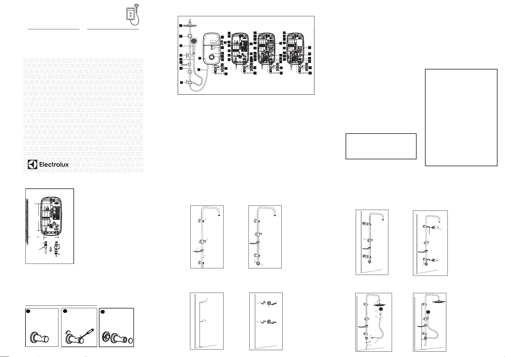
1. PARTS IDENTIFICATION
1. Front Cover
2. LED Indicators
i) Earth LED Indicator
ii) Power/ELCB Indicator
3.
Test / Reset Button
4.
Face Panel
5. Pump Button*
6. Temperature Control Knob
7. 3 in 1 Stop Valve
i) Stop Valve Lever
ii) Flow Regulator Valve Adjustment
iii) Built-in-Filter
8. Mesh Filter
9. Rain Shower Head
10.
Rail Bracket
11.
Handshower
12. Adjustable Shower Holder
13.
PVC Hose (1.5 meter)
14. Soap Tray
15. Slider Rail
16. PVC Hose (1.0 meter)
Fig 1.
9
10
11
12
13
14
15
17
16
18
19
21
22
25
23
27
28
29
20
OFF
7
8
18
19
21
22
25
24
24
26
27
28
29
20
OFF
7
8
1
3
6
4
5
OFF
7
8
31
27
28
29
OFF
7
8
32
2.
SAFETY INFORMATION
2.1 Products manufactured by Electrolux are safe
provided they are installed, used and maintained
in good working order in accordance with our
instructions and recommendations. Always refer
to this manual if you have any doubt.
2.2 The appliance must be earthed. Improper
grounding could cause electrical shock.
2.3 If any of the following conditions occur as
shown below, immediately switch off the power
supply and contact the Electrolux Consumer
2.6 When the Instant Hot Shower is used by
someone such as child, elderly person, sick person
and
physically handicapped person, the person
concernedis kindly requested to pay attention and
check the shower temperature by hand from time
to time. User is advised to test and adjust the water
temperature before using.
2.7During lightning/thunder, switch off the power
supply to the Instant Hot Shower in advance to protect
the Instant Hot Shower against possible damage.
2.8 The earth continuity conductor of the electrical
installation must be effectively connected to all
exposed metal parts of
other appliances and services
in the room, which in the Inst
ant Hot Showeris to be
installed to conform to local regulations and ensure
proper earthing/grounding for ELCB to be effective.
NOTE: When removing the Instant Hot Shower
from package, a small amount of water may be
found inside. This is normal as the Instant Hot
Shower is tested during manufacturing process.
WARNING !
.
.
.
.
.
If the Instant Hot Shower begins to make an odd
noise, smell or smoke.
If ELCB trips and Instant Hot Shower Indicator
does not light up.
Water temperature cannot be controlled.
If the Instant Hot Shower shows signs of a distinct
change in performance.
If water leaks from inside.
2.9 WARNING : Metallic / chromed hose and
conductive control valve shall not be used.
2.10Installation must be carried out by a qualified
personnel and in compliance local authority
2.11 This Instant Hot Shower must be permanently
connected to the direct main line supply. A plug
and socket is not recommended to be used.
2.12For the correct size of wire conductor
corresponding to different electrical loadings, please
2.13This Instant Hot Shower operates at a minimum
water flow rate of 2.0 litre/min and maximum working
pressure of 6 bars. For direct connection from the
water tank
, the Instant Hot Shower must have an
2.14
The Instant Hot Shower will not function if there
is insufficient water flow (min 2.0 litre/min) to trigger
2.15
The buil
t-in ELCB will automatically cut off the
power supply in case there is a current leakage over
2.16
The thermostat will automatically cut off the
power supply if it has sensed an abnormal rise in
water temperature.
CAUTION !
regulations.
refer to Table 1.
installation minimum 1.0m below the water tank.
the flow switch.
15mA.
Care Center. Never attempt to repair the Instant
Hot Shower yourself:
2.5 For Pump Model, it is highly recommended
to connect the Water Inlet Connection to tank
storage supply, otherwise it may cause damage
to the Pump Motor.
Fig.3
RAIL BRACKET COVER & CAP DISMANTLE STEPS
1
RAIL BRACKET
2
OPEN THE RAIL
BRACKET COVER
BY TURNING ANTI
CLOCKWISE &
USING SCREW
DRIVER TO OPEN
THE CAP
3
RAIL BRACKET
COVER
COME-OUT
3.
HEATER UNIT INSTALLATION
RAIN SHOWER SET INSTALLATION PROCEDURES
connect to
water outlet
connection
INSTANT HOT SHOWER
UNIT INSTALLATION DIAGRAM
Fig. 2
Screw
A
3 in 1
stop valve
inlet
Wall
285.5mm
Washer
connect to
water inlet
connection
Min.
80 mm
150mm
OFF
3.1 Select a suitable position in the bathroom.
3.2 Remove the screw (A) at the bottom of the
Instant Hot Shower
. (Fig. 2)
3.3 Remove the Front Cover from the bottom and then lift up the front cover.
3.4 Mark 3 Screw points of the Heater Base on the wall. The
Instant Hot Shower
position
should be 1.5m above the bathroom floor.
3.5 Use 6mm diameter drill and make the wall plug holes in depth of 34mm.
3.6 Insert the wall plugs and mount the
Instant Hot Shower
firmly in position with the screws
provided.
shower
holder
rail bracket
slider rail
selector valve
38mm
38mm
1300mm
650mm
wall plug hole
screw
mounting terminal
1.
2.
3.
4.
STEP 1
Insert the Top Rail Bracket, Adjustable
Shower Holder , Soap Tray & Bottom
Rail Bracket to the Slider Rail.
STEP 2
Connect the Selector Valve to the
bottom of Slider Rail.
STEP 3
Select a suitable position for the Rain Shower
Set then mark 4 screws point (2 on top and 2
on bottom).The gap of 2 screw hole was 38mm.
It is recommended that the Top Rail Bracket
position at height of 1950mm to the floor and
Bottom Rail Bracket 1300mm to the floor.
wall plug
STEP 4
Use 6mm diameter drill and make the wall plug
holes in depth of 34mm. Insert the wall plugs
and mounting terminal firmly in position with
the screw provided.
RAIN SHOWER SET INSTALLATION
PROCEDURES (CONT’D)
soap
tray
rail
bracket cap
hexagon tool
plastic nut
STEP 5
Mount the Slider Rail (connected with Rail
Bracket, Adjustable Shower Holder and Selector
Valve) to the mounting terminal by turns the
terminal cover.
5.
6.
STEP 6
Remove the cover and cap from the Rail Bracket
(Fig. 3A) and screw the rail bracket by turning the
cover clockwise. Using hexagon tool to tighten the
plastic nut to the desire position and then replace
the cover.
1200mm
650mm
100mm
PVC hose
rain
shower
head
shower
head
7.
8.
STEP 7
Connect the Rain Shower Head to the top of
Slider Rail, 1.5Meter PVC Hose to Hand Shower
Head and 1Meter PVC Hose to the Heater.
Connected be sure to put in the Rubber Washer.
STEP 8
Recommended Height for Rain Shower Set.
rail bracket
cover
rubber
washer
RAIN SHOWER SET INSTALLATION
PROCEDURES (CONT’D)
No Pump model AC Pump model DC Pump model
18
19
21
22
20
33
25
24
33
17. Selector Valve
18. Heater Base
19. Terminal Block
20. Thermostat (Double-Action)
21. PCB Board (Test & Reset)
22. Heater Tank
23. VR Board
24. Main/ELCB Board**
25. Water Outlet Connection
26. AC Pump*
27. TRIAC
28. Reed Switch Assy
29. Water Inlet Connection
30. SMPS PCB Board
31. D.C. Silent Pump*
32. Rating Label
33. Pump Board
REV 1
2
*
*
*
* For Pump Model only
** Pump Model VR Board & Main/ELCB Board combine.
2.4 If the Red (POWER) Indicator does not go off
when you turn off the water, switch OFF the
mains supply and contact Electrolux Consumer
Care Centre for repair service.Special skill is
required for repairing.
NEVER try to repair the unit by yourself.
* **
* **
**
**
Produktspecifikationer
| Varumärke: | Electrolux |
| Kategori: | Pannor & pannor |
| Modell: | EWE361KB-DWB1 |
| Färg på produkten: | Zwart |
| Vikt: | 2200 g |
| Bredd: | 383.54 mm |
| Djup: | 256.54 mm |
| Höjd: | 25.4 mm |
| Batterikapacitet: | 3270 mAh |
| Blåtand: | Nee |
| Skärm diagonal: | 15.6 " |
| Upplösning: | 1366 x 768 Pixels |
| Pekskärm: | Nee |
| Original bildförhållande: | 16:9 |
| Processorfrekvens: | 2 GHz |
| Processorfamilj: | Intel® Core™ i3 |
| Processormodel: | i3-5005U |
| Antal processorkärnor: | 2 |
| Wi-Fi-standarder: | 802.11a, Wi-Fi 5 (802.11ac), 802.11b, 802.11g, Wi-Fi 4 (802.11n) |
| Vormfaktor: | Clamshell |
| Inkluderar operativsystem: | ChromeOS |
| Ethernet LAN: | Nee |
| Integrerad minneskortläsare: | Ja |
| Kompatibla minneskort: | SD |
| Processor litografi: | 14 nm |
| fingeravtrycksläsare: | Nee |
| Inkluderar AC-adapter: | Ja |
| LED-bakgrundsbelysning: | Nee |
| Antal USB 2.0-portar: | 1 |
| Antal HDMI-portar: | 1 |
| DVI-port: | Nee |
| Monteringsalternativ för kabellås: | Nee |
| AC-adapter, ström: | 65 W |
| HD typ: | HD |
| Inbyggd mikrofon: | Ja |
| Internminne: | 4 GB |
| Förvarings media: | SSD |
| Batteritid/batteritid: | - uur |
| Internminnestyp: | DDR3L-SDRAM |
| WiFi-standard: | Wi-Fi 5 (802.11ac) |
| Intel® Wireless Display (Intel® WiDi): | Ja |
| Antal portar USB 3.2 Gen 1 (3.1 Gen 1) Typ A: | 1 |
| Processoruttag: | BGA 1168 |
| Stepping: | F0 |
| Systembuss: | 5 GT/s |
| Processor antal trådar: | 4 |
| PCI Express-kortplatsversion: | 2.0 |
| Processorns driftlägen: | 32-bit, 64-bit |
| Processorns cache: | 3 MB |
| Tjunction: | 105 °C |
| Busstyp: | DMI2 |
| PCI Express-konfigurationer: | 2x4, 4x1 |
| Thermal Design Power (TDP): | 15 W |
| Kodnamnsprocessor: | Broadwell |
| Maximalt antal PCI Express-linjer: | 12 |
| Typ av processorcache: | Smart Cache |
| ECC stöds av processor: | Nee |
| Processorfabrikant: | Intel |
| Konfigurerbar TDP-ned: | 10 W |
| Konfigurerbar TDP ned frekvens: | 0.6 GHz |
| Maximalt internminne: | - GB |
| Total lagringskapacitet: | 32 GB |
| Typ av optisk enhet: | Nee |
| Inbyggd grafikadapter: | Ja |
| Familjens inbyggda grafikadapter: | Intel® HD Graphics |
| Inbyggd grafikadaptermodell: | Intel® HD Graphics 5500 |
| Grundläggande frekvens inbyggd grafikadapter: | 300 MHz |
| Inbyggd grafikadapter dynamisk frekvens (max): | 850 MHz |
| Inbyggt grafikkort-ID: | 0x1616 |
| Maximalt minne inbyggd grafikadapter: | 16 GB |
| Inbyggd grafikadapter DirectX-version: | 11.2 |
| Fram kamera: | Ja |
| Numerisk knappsats: | Nee |
| Instruktionsuppsättningar som stöds: | AVX 2.0, SSE4.1, SSE4.2 |
| Intel® My WiFi Technology (Intel® MWT): | Nee |
| Intel® Smart Response Technology: | Ja |
| Intel® Hyper Threading Technology (Intel® HT Technology): | Ja |
| Intel® Turbo Boost-teknik: | Nee |
| Intel® Quick Sync-videoteknik: | Ja |
| Intel® InTru™ 3D-teknik: | Ja |
| Intel® Clear Video HD-teknik (Intel® CVT HD): | Ja |
| Intel® Insider™: | Ja |
| Intel® Flex Memory Access: | Ja |
| Intel® AES nya instruktioner (Intel® AES-NI): | Ja |
| Förbättrad Intel SpeedStep-teknik: | Ja |
| Kör Disable Bit: | Ja |
| Idle stater: | Ja |
| Termisk övervakningsteknik: | Ja |
| CPU-konfiguration (max): | 1 |
| Intel® Enhanced Halt State: | Ja |
| Intel® Clear Video Technology för mobila internetenheter (Intel® CVT för MID): | Ja |
| Intel® VT-x med utökade sidtabeller (EPT): | Ja |
| Inbyggda alternativ tillgängliga: | Nee |
| Grafik & IMC litografi: | 14 nm |
| Intel® Small Business Advantage (Intel® SBA): | Ja |
| Intel® Secure Key: | Ja |
| Intel® 64: | Ja |
| Intel® OS Guard: | Ja |
| Intel® Virtualization Technology for Directed I/O (VT-d): | Ja |
| Intel® Clear Video-teknik: | Ja |
| Intel® Virtualization Technology (VT-x): | Ja |
| Processorpaketstorlek: | 40 x 24x 1.3 mm |
| Konfliktfri processor: | Ja |
| Intel® Identity Protection Technology (Intel® IPT): | Ja |
| Versie Intel® Identity Protection Technology: | 1.00 |
| Versie Intel® Secure Key Technology: | 1.00 |
| Versie Intel® Smart Response Technology: | 1.00 |
| ARK ID-processor: | 84695 |
| Intel® Trusted Execution Technology: | Nee |
| Intel® TSX: | Nee |
| Intel® Stable Image Platform Program (SIPP): | Nee |
| Versie Intel® Stable Image Platform Program (SIPP): | 0.00 |
| Intel® TSX-NI-version: | 0.00 |
| Intel® Anti-Theft Technology (Intel® AT): | Nee |
| Anslutning till basstation: | Nee |
| SmartCard-kortplats: | Nee |
| Processorkod: | SR27G |
| Antal installerade SSD:er: | 1 |
| SSD-kapacitet: | 32 GB |
| Pekdon: | Touchpad |
| Windows-tangenter: | Ja |
| FSB-paritet: | Nee |
| Bussprocessor på framsidan: | - MHz |
| Intel® efterfrågebaserad växling: | Nee |
| Typ av laddningsport: | DC-in ingang |
| Typ CardBus PCMCIA-slot: | Nee |
| Processorserie: | Intel Core i3-5000 Mobile series |
| ExpressCard-kortplats: | Nee |
| S/PDIF-utgång: | Nee |
| Höjd (fram): | 24.13 mm |
| Höjd (bak): | 24.13 mm |
| Intel® Dual Display Capable Technology: | Nee |
| Intel® FDI-teknik: | Ja |
| Intel® Rapid Storage Technology: | Nee |
| Intel® Fast Memory Access: | Ja |
| Intel® Smart Cache: | Ja |
| Intel® Small Business Advantage (SBA)-version: | 1.00 |
| Intel® segmenttaggning: | Onderwijs |
| Intel® Virtualization Technology (Intel® VT): | VT-d, VT-x |
| LightScribe: | Nee |
| Wifi: | Ja |
| Typ produkt: | Chromebook |
| Batteriteknik: | Lithium-Ion (Li-Ion) |
| Antal battericeller: | 4 |
| Processorgenerering: | Vijfde generatie Intel® Core™ i3 |
Behöver du hjälp?
Om du behöver hjälp med Electrolux EWE361KB-DWB1 ställ en fråga nedan och andra användare kommer att svara dig
Pannor & pannor Electrolux Manualer

17 September 2024
17 September 2024
17 September 2024
17 September 2024
17 September 2024
17 September 2024
17 September 2024
17 September 2024
19 Juli 2024
19 Juli 2024
Pannor & pannor Manualer
Nyaste Pannor & pannor Manualer
9 April 2025
9 April 2025
9 April 2025
1 April 2025
31 Mars 2025
13 Mars 2025
10 Mars 2025
10 Mars 2025
4 Mars 2025
4 Mars 2025