Electrolux EWE361LA-DAX4 Bruksanvisning
Electrolux Pannor & pannor EWE361LA-DAX4
Läs gratis den bruksanvisning för Electrolux EWE361LA-DAX4 (3 sidor) i kategorin Pannor & pannor. Guiden har ansetts hjälpsam av 13 personer och har ett genomsnittsbetyg på 4.9 stjärnor baserat på 7 recensioner. Har du en fråga om Electrolux EWE361LA-DAX4 eller vill du ställa frågor till andra användare av produkten? Ställ en fråga
Sida 1/3
ENELECTRIC WATER HEATERUSER MANUAL
EWE361LA-DAX4
EWE361LX-DBX4
EWE361LB-DIX4
2.SAFETY INFORMATION
2.1 Prcaroduts mnufactued by Electrolux are safe
providedthey are insted,used ndintinall a maaed
in god working in acoorder corda oncewith ur
instructonsand eci rommendatinsways efer o. Alr
t ma ve yo. o thisnualifyouhaan dubt
2.2 T . heElectric Water Heater must beearthed
Impper rogroundinuldusetralshockg co ca elecic .
2.3 yollioc Ifan of the fowng conditins ocur as
shown below, imi sw ofe medatelyitchf thpower
supply cc and ontat the ElectroluxConsumer
2.6 When theElectric Water Heater is
used by one susomech as child, elderly
person,ca sik person nd physically
handicapped eperson, th person
conkindly equestcerned is red toy pa
attention nd shr acheck the owe
teramperatue by hnd fto tirom time me.
2.Durinightning7g l/thunder,cff swith othepower
suppthly to e Electric Water Heaterin advance t o protcte
the Electric Water Heater against possible damage.
2.8 The ity cc leal earthcontinuondutorofthe ectric
instalatilo effelon must bectivey cnnected to all
eed metal xpospartsofotherppl aiances and
servicesoom,whih rin the cin th
e Electric Water
Heaterinstalonf oe is t blced to orm to local
reand rprggulations ensue oper earthin/gounding r
for ELCB to be effective.
NOTE: rem When ovintheg Electric Water Heater
froe, a aat mae m ckpaagsmll mounofwatery b
found inside. This is normal as the Electric Water
Heater is itested durng anufaturinmcg pro. cess
WARNING !
.
.
.
.
.
If the begins to make an Electric Water Heater
odd noise, smell or smoke.
If ELCB trips and Indicator Electric Water Heater
does not light up.
Water temperature cannot be controlled.
If the shows signs of a Electric Water Heater
distinct change in performance.
If water leaks from inside.
2.10Instatillaom caion ust berred utby a
qualified persnnempianccalol and in cole lo
2.11 Thi s Electric Water Heatermust be
permnenty connectethald to er diectain m line
supply. l cket t roeed A pugand sois noecmmnd
t ed.o beus
2.12For rthe corect size of wire conductor
creoingo frorspnd tdifeent ctrioadings,elecal l
2.13Thi erates a s Electric Water Heateropat
mimw ow enium aterflrat of 2.0 tre/limin and
maxioring mum wkprerof . For ssue 6 bars
direct connctitheon from e te war tank, the
2.14
The l on Electric Water Heaterwilnot functi
ris iif thee
nsufficientter wa ow (n 2.lre/mflmi0 itin)
2.15
Thebui lt-in ELCB will automatically cut off
the uppn power sly icaseres a r the icurent
2.16
Thethrmstat tiy ut eowiomall autcallc off the
power iit see oi supplyf hasnsd anabnrmal rsein
were.atr temperatu
CAUTION !
authorty iregultinsao.
pse releaefr to Table 1.
Electric Water Heater mt ve ushaan
inston nium altilamim1.0m ow e w.belthater tank
to trir the ggeflow switch.
leageka over 15mA.
Care Center. Never attempt to repair the Electric
Water Heater yourself:
2.5 For Pump Model, it is highly recommended
to connect the Water Inlet Connection to tank
storage supply, otherwise it may cause damage
to the Pump Motor.
User io e s advised t testand adjust th
wer mratteperatue befngorie us.
2.9 WARNING : Metallic / chromed hose and
conductive control valve shall not be used.
REV 1
3.
ELECTRIC WATER HEATER UNIT INSTALLATION
3.1 Select a suitable position in the bathroom.
3.2 Remove the screw (A) at the bottom of the
Electric Water Heater
. (Fig. 2)
3.3 Remove the Front Cover from the bottom and then lift up the front cover.
3.4 Mark 3 Screw points of the Heater Base on the wall. The
Electric Water Heater
position should be
1.5m above the bathroom floor. (Fig. 2)
3.5 Mark 2 screw points of the Slider Rail beside the
Electric Water Heater
. It is recommended that the
top of the portion is in level with the top of
Electric Water Heater
. (Fig. 3)
3.6 Use 6mm diameter drill and make the wall plug holes in depth of 34mm ,for mount the Electric
Water Heater.
3.7 Insert the wall plugs and mount the
Electric Water Heater
firmly in position with the screws provided.
3.8 Insert the Shower Holder and Soap Tray into the Slider Rail.
3.9 Insert the Rail Bracket to both end of the Slider Rail Bar.
3.10 Remove the cap from the Rail Bracket and screw the Bracket to marked position.
Replace the cap. (Fig. 3)
Fig. 3
connect the
hand shower
to flexible hose
SHOWER SET INSTALLATION DIAGRAM
Flexible Angle
Adjustment
5 Spray
Patterns
Selection
Hand
Shower
Flexible
Hose
Soap Tray
Slider Rail Bar
Adjustable
Shower
Holder
Screw
Wall Plug
Mounting
Terminal
connect to
water outlet
connection
Rail bracket cap
Hexagon tool
(Tighten plastic nut before close cap)
Plastic nut
Fig 3A
RAIL BRACKET COVER & CAP DISMANTLE STEPS
1
RAIL BRACKET
2
OPEN THE RAIL
BRACKET COVER
BY TURNING ANTI
CLOCKWISE &
USING SCREW
DRIVER TO OPEN
THE CAP
3
RAIL BRACKET
COVER COME-OUT
4. PLUMBING PROCEDURE
CAUTION!
IMPORTANT
This Electric Water Heater is a single point
system and the “Water Outlet” can only be
fitted to the Hose and Handshower set
provided. MUST NOT TO CONNECT
CONTROL VALVE OR FITTING CAN BE
FITTED TO THE WATER OUTLET.
WARNING!
5.
ELECTRICAL INSTALLATION
WARNING!
PROCEDURE :
5.7 Connect the cable as following: (Fig. 5)
BROWN or RED --LIVE (L)
BLUE or BLACK --NEUTRAL (N)
GREEN or GREEN/YELLOW --EARTH ( )
5.8 Clamp the cable to the correct position.
Technician need to confirm the wire before
installation.
CHECK IF THE WIRING CONNECTION IS
CORRECT and replace the cover.
5.9 When putting back the Front Cover,
please take note of the procedure shown below :
-Ensure the position is correct, turn the
Temperature Control Knob Insert to OFF
position as shown in Fig.A (At the Heater Base)
5.1 This Electric Water Heater must be
earthed. Improper grounding could cause
electrical shock.
5.2 Remember to SWITCH OFF the power
supply before carrying out any electrical work.
5.3 Refer to TABLE 1 for the correct cable size.
5.4 Use double insulation cable of over 4.0mm²
5.5 Lead the power cable from MCB to a
“ON/OFF’’ double pole Linked Switch having a
contact separation of at least 3mm in all poles
outside the bathroom, then lead a cable to the
terminal block inside the Electric Water Heater.
(Fig. 4)
5.6 Insert the wall embedded cable through
Side Entry ‘A’ by cutting a hole at the source
cord rubber holder and lead the cable to
Cable Bracket ‘B’. (Fig. 6)
Always KEEP the water supply to the Electric Water
Heater free from mud and dirt at all time during usage.
4.1 Connect the 3 in 1 Stop Valve to the Water
Inlet with washer. Use correct tools to tighten
and be careful not to over tighten and damage
the plastic nut.
4.2 Connect the incoming water piping to the 3 in
1 Stop Valve (1/2” BSP).
Make sure to put the Mesh Filter between 3
in 1 Stop Valve and incoming water piping.
4.3
If in any case, the 3 in 1 Stop Valve is not use or
omitted, make sure to put the Mesh Filter
between the Electric Water Heater inlet pipe
and incoming water pipe.
4.4 Turn on the water mains to drain out all plumbing
dirts before connecting the water supply to the
Electric Water Heater, the water supply to the
Electric Water Heater must be free from mud and
dirt.
4.6 Hook the Handshower to the Slider Rail
Shower Holder and adjust to your ideal position.
4.7 Check if any water leakage.
4.8 Do not use sealing tape during piping
installation.
THE HEATER TANK MUST BE FILLED UP WITH
WATER BEFORE TURNING ON THE POWER
SUPPLY TO PREVENT ANY DRY BURNT DAMAGE
TO THE HEATING ELEMENT.
4.5 Connect the Hose and Handshower to the
outlet of Electric Water Heater, be sure to put in the
Washer in between the connection. (Fig. 2)
4.10 DO NOT APPLY PLUMBING CEMENT ON
CONNECTION. WHENEVER NECESSARY, USE
ONLY THREAD OR SEALING TAPE.
4.9 THE WATER INLET AND OUTLET MUST BE
INSTALLED CORRECTLY, OTHERWISE ELECTRIC
WATER HEATER WILL NOT FUNCTION.
5. ELECTRICAL INSTALLATION (CONT’D)
6. TABLE 1 - CABLE SIZE TABLE
Power Current
(kW) (A)
Conductor Size (csa)
mm Conduit Cable Flexible Cable
On/ Off Fuse /
Switch (A) MCB (A)
2
Voltage
(AC)
3.6 15.0 4.0 7 / 0.85mm 56 / 0.30 mm 20 20
240V ~
50/60 Hz
(Malaysia Model)
METHOD OF ALIGNMENT WHEN REPLACING FRONT COVER
Cable
Fig. 4
Brown or Red = Live (L)
Blue or Black = Neutral (N)
Green or Green/ Yellow = Earth ( )
Fig. 5
Fuse Distributor Board
Miniature Circuit Breaker (MCB)
ON/OFF Double Pole Switch
Double PVC cable
NOTE:
Refer to TABLE 1 for electrical loading and
correct size of wire conductor
Front Cover
Fig A
Fig B
F
A
B
Fig. 6
Position
this Way
FF
Position
this Way
12
3
4
5
9
10
12
13
11
14
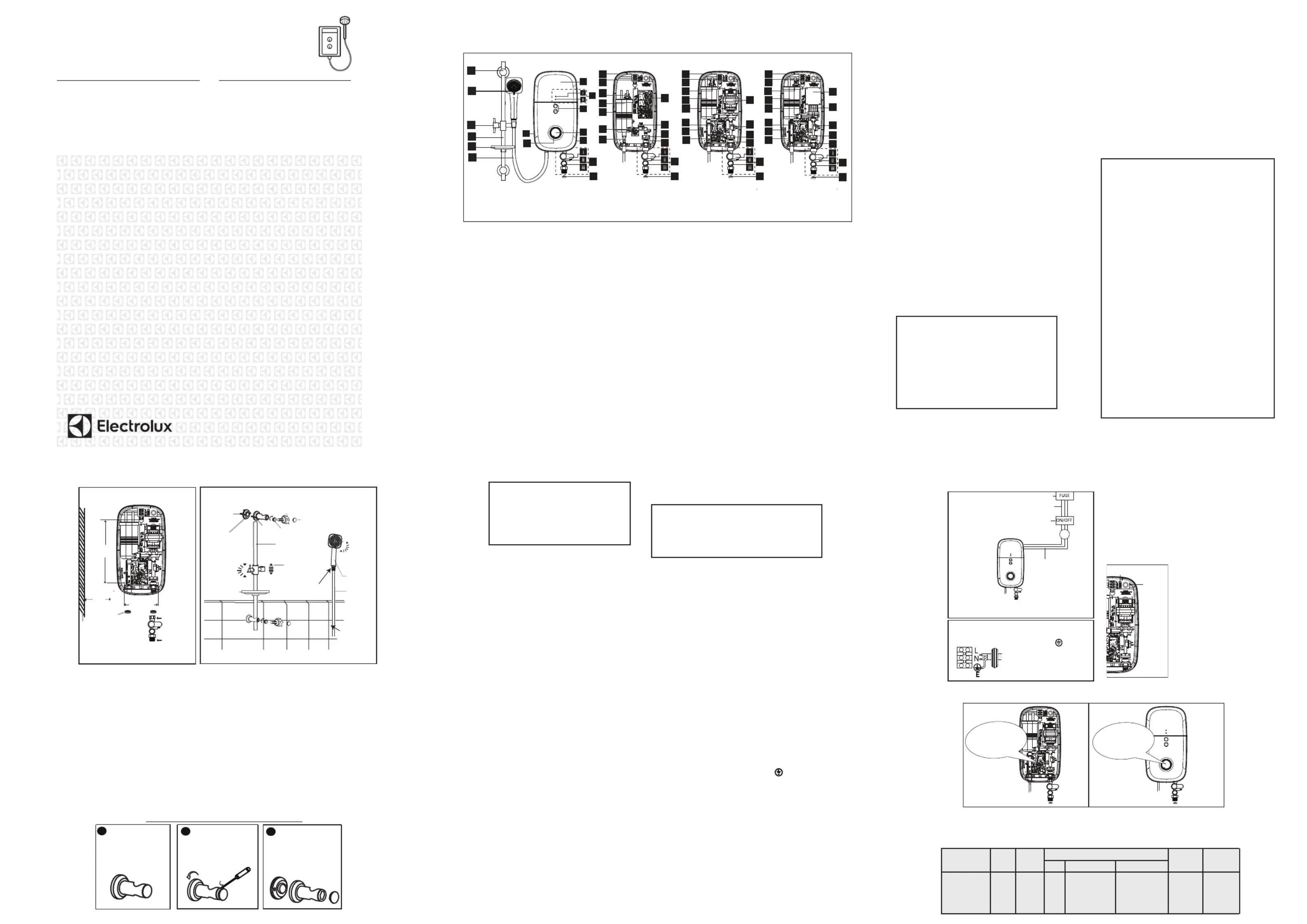
1. PARTS IDENTIFICATION
1. Front Cover
2. LED Indicators
i) Earth LED Indicator
ii) Power/ELCB Indicator
3.
Test / Reset Button
4.
Rating Label
5. Pump Button*
6. Temperature Control Knob
7. 3 in 1 Stop Valve
i) Stop Valve Lever
ii) Flow Regulator Valve Adjustment
iii) Built-in-Filter
8. Mesh Filter
9. Rail Support
10.
Handshower
11.
Adjustable Shower Holder
12. Slider Rail
13.
PVC Hose
14.
Soap Tray
15. Heater Base
16. Terminal Block
17. Thermostat (Double-Action)
18. Heater Tank
19. PCB Board (Test & Reset)
20. VR Board
21. Main/ ELCB Board**
22. Water Outlet Connection
23. AC Pump*
24. TRIAC
25. Reed Switch Assy
26. Water Inlet Connection
27. SMPS PCB Board
28. D.C. Silent Pump*
29. Pump Board
30. Temperature Knob LED Light
15
16
18
19
22
21
23
24
25
26
OFF
7
8
27
24
25
26
OFF
7
8
28
No Pump model
24
25
26
OFF
7
8
AC Pump model
DC Pump model
Fig. 1
15
16
18
19
22
20
21
17
17
15
16
18
19
22
21
17
OFF
7
8
1
3
6
4
29
29
5
*
*
*
2
connect to
water outlet
connection
ELECTRIC WATER HEATER
UNIT INSTALLATION DIAGRAM
Fig. 2
Screw
A
3 in 1
stop valve
inlet
Wall
285.5mm
Washer
connect to
water inlet
connection
Min.
80 mm
150mm
OF
* For Pump Model only
** Pump Model VR Board & Main/ELCB Board combine.
2.4 If the Red (POWER) Indicator does not go off
when you turn off the water, switch OFF the
mains supply and contact Electrolux Consumer
Care Centre for repair service.Special skill is
required for repairing.
NEVER try to repair the unit by yourself.
* **
* **
**
**
30
-
Install the Front Cover,turn the Temperature
Control Knob to OFF position to align with the
VR shaft as shown in Fig.B (At the Front Cover)
5.10 Fix the Temperature Control Knob and
screw ‘A’ (Fig. 2).
Reconnect the Temperature Knob LED Light
wire to Main Board (J5 Connector).
Produktspecifikationer
| Varumärke: | Electrolux |
| Kategori: | Pannor & pannor |
| Modell: | EWE361LA-DAX4 |
| Färg på produkten: | Wit |
| Inbyggd display: | Ja |
| Timer: | Ja |
| Vikt: | 9800 g |
| Bredd: | 260 mm |
| Djup: | 260 mm |
| Höjd: | 800 mm |
| Förpackningens vikt: | 11500 g |
| Förpackningens bredd: | 436 mm |
| Djuppackning: | 317 mm |
| Förpackningshöjd: | 890 mm |
| Lämplig för: | Binnen |
| Justerbar termostat: | Nee |
| Fjärrstyrd: | Ja |
| Fjärrkontroll ingår: | Ja |
| AC-ingångsspänning: | 230 V |
| AC-ingångsfrekvens: | 50 Hz |
| Värmekraft: | - W |
| Placeringsalternativ: | Vloer |
| Värmeeffekt (min): | - W |
| Antidammfilter: | Ja |
Behöver du hjälp?
Om du behöver hjälp med Electrolux EWE361LA-DAX4 ställ en fråga nedan och andra användare kommer att svara dig
Pannor & pannor Electrolux Manualer

17 September 2024
17 September 2024
17 September 2024
17 September 2024
17 September 2024
17 September 2024
17 September 2024
17 September 2024
19 Juli 2024
19 Juli 2024
Pannor & pannor Manualer
Nyaste Pannor & pannor Manualer
9 April 2025
9 April 2025
9 April 2025
1 April 2025
31 Mars 2025
13 Mars 2025
10 Mars 2025
10 Mars 2025
4 Mars 2025
4 Mars 2025