Electrolux EWE361MA-DST1 Bruksanvisning
Electrolux Pannor & pannor EWE361MA-DST1
Läs gratis den bruksanvisning för Electrolux EWE361MA-DST1 (2 sidor) i kategorin Pannor & pannor. Guiden har ansetts hjälpsam av 12 personer och har ett genomsnittsbetyg på 5.0 stjärnor baserat på 6 recensioner. Har du en fråga om Electrolux EWE361MA-DST1 eller vill du ställa frågor till andra användare av produkten? Ställ en fråga
Sida 1/2
ENELECTRIC WATER HEATERUSER MANUAL
EWE241MX-DST2
EWE381MX1DST2
EWE451MX-DST2
EWE451MB-DST2
EWE481MX1DST2
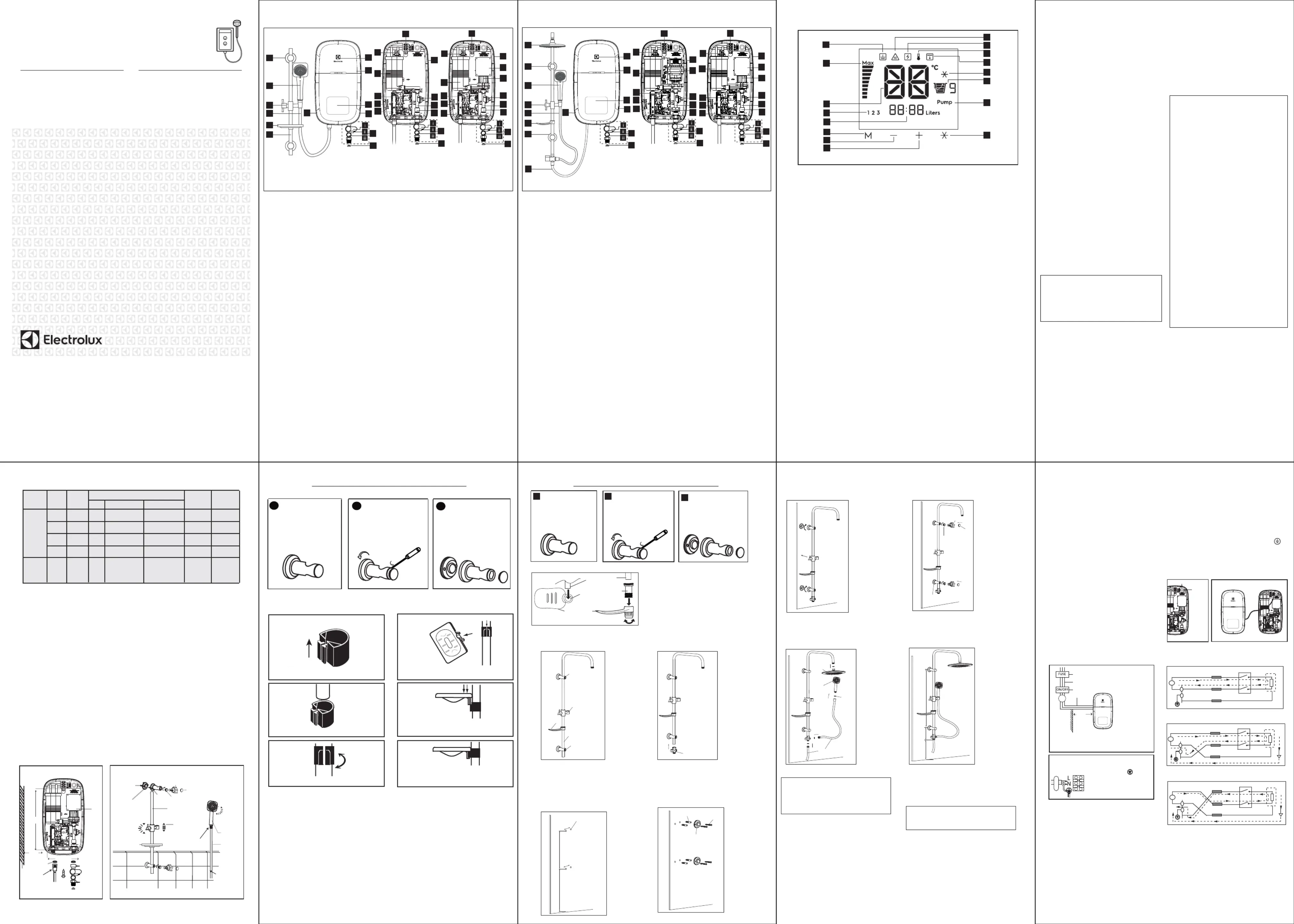
1. PARTS IDENTIFICATION (NORMAL SHOWER MODEL)
1. Front Cover
2. Main Display
(*LED Display Main PCB
Board behind front cover)
3. 3 in 1 Stop Valve
i) Stop Valve
ii) Flow Regulator Valve
iii) Built-in-Filter
4. Mesh Filter
5. Rail Support
6. Handshower
7. Adjustable Shower Holder
8. PVC Hose
9. Soap Tray
10. Slider Rail
11. Terminal Block
12. Thermostat (Double-Action)
13. Heater Tank
14. PCB Board (Test & Reset)
15. ELCB Board
16. Water Outlet Connection
17. SMPS PCB Board*
18. DC Pump*
19. Heater Base
20. Triac
21. Flow Sensor
22. Water Inlet Connection
23. Rating Label
24. Test & Reset Button
25. Logo Light
Fig 1. (Thailand, Indonesia, Philippines & Vietnam model)
*
Note : (*) For DC PUMP
*
No Pump modelDC Pump model*
19
17
20
18
22
21
14
13
16
19
20
22
21
13
14
16
1
2
5
6
7
8
9
10
11
24
23
2. DESCRIPTION OF LCD DISPLAY AND CONTROL PANEL
1. Earth Icon
2. Power Display Bar
3. Temperature Indicator
4. Memory Indicator
5. Litre for EcoShower
6. rMemoy Button
7. Temperature (-) Button
8. Temperature (+) Button
9. Overheat Icon
10. ELCB Icon
11. Thermistor Icon
12. Low Water Pressure Indicator
13. Cold Shower Icon
14. EcoShower Counter
15. Pump Indicator
16. Cold Shower Button
Notes:
1. Memory includes temperature.
2. Buttons are 100% lit when unit is ON and buttons are not lit when unit is OFF or standby mode.
3. The display and buttons should not blink, unless there is an urgent message/ error/ alarm.
While normal operation all interactions shown without the screen segments blinking.
1
2
3
4
5
6
7
8
9
10
11
12
13
14
15
16
Fig. 1a
3. SAFETY INFORMATION
3.1 Products manufactured by Electux are safe rol
provided they are installed, used and maintained in
instructions and recodations. Always refer mmen
to this manual if you have any doubt.
WARNING !
3.2EARTHING :
A) The Eartng instlation ld be ced out in hialshouarri
accance with the al Wng lations.ordlociriRegu
B) The Electric Water Heater must be earthed.
Ier ng such as Earth cuctor not mpropgroundiond
groundined (floatg) or having gh isthires
ance to
grouound cld cause malfunction to ELCB and
electrical shock. Never use water heater if tre is he
dohiubt on Eartng instlation. al
good working order in accordance with our
3.3 If any of the following conditions occur as
contact the Electux Custer Svice Call Centre. rolomer
Never attempt to ir the unit elf : repayours
.
.
.
.
.
If the Electric Water Heater begins to make an
odd noise,smell or smoke.
If ELCB trips and LCD display does not light up.
Water temperature cannot be controlled.
If the Electric Water Heater shows signs of a
distinct change in performance.
If water leaks from inside.
swn below, immediately switch off the mains and ho
3.5 For Pump el, it is ly re Modhigh
ced ommend
to cnect the Water Inlet nection to stge onConora
water tank , otwise it may cause ge to the herdama
built in Pump Motor inside.
3.6When the
Shower is ed by someone such us
as child, derly rson, sick rson and physically elpepe
hanpedicapped rson, the rson concerned is pe
dly rkinequested to pay attention and check the
shower temperature by hand from time to time.
User is advised to test and just the waterad
temrature bepe
fore using.
3.7 During taking shower , once stop for a while
for washing with soap or shampoo and resuming
the shower again by turning on 3 in 1 stop valve
or water tap, it is normal that the instant water
temperature output from the water heater will be
higher than the set temperature.To avoid the risk
of scalding, it is advisable to avoid shower with
water output in that period, or let the water flow
for few seconds before continuing bathing.
3.8
During lightning/thunder, switch off the electric
supply to the shower unit in advance to protect the
shower unit against posble damage.si
NOT
E
: When removing the unit from package,
a small amount of ense water may be fnd condou
inside. This is normal as the unit is tested during
3.10Installation must be carried out by a
qualied personnel and in compliance local fi
CAUTION !
manufacturing process.
authority regulations.
For the
correct size of wire conductor
corresponding to different electrical lgs, oadin
please refer to Tle 1. ab
This Electric Water Heater operates
at a minimum water ow rate of 2.0 litre/min fl
and maximum working pressure of 6 bars.
For direct connection from the stge water ora
tank, the Electric Water Heater must have an
installation minimum ght 1.0m below the hei
stge water tank. ora
The built-in ELCB ll automatlwiical
y cut
o the er supply in case there is a current ffpow
leakage over 15mA rds.upwa
The thermostat will automatically cut off
the power supply if it has sensed an abnormal
rise in water temrature. pe
The Electric Water Heater will not
function if there is insufcient water ow fifl
(min 2.0 liters/min) to trigger the flow ssor. en
3.12
3.13
3.15
3.16
3.14
his Electric Water Heater must be
permanently ected to the direct main conn
line
supply.
B) Recommended to install a er switch for pow
easily to switch ON & OFF the er ly to powsupp
electric water heater before and after use.
C) Housld ns switch box must have a ehomai
working ELCB (Incoming ns er smaipowupply)
with RCD esue ent e) of 10mA.(ridcurrdevic
3.11A) T
3.9 WARNING :
A) Metallic / chromed hose and conductive
control valve shall not be used.
B) Must use 3 in 1 Stop Valve accessories
provided with the electric water heater.
5.
ELECTRIC WATER HEATER UNIT INSTALLATION
5.1 Select a suitable position in the bathroom.
5.2 Remove the screw (A) at the bottom of the unit. (Fig. 2)
5.3 Remove the Front Cover by lifting up the front cover from the bottom and be careful not to
over pull
5.4 Mark 3 Screw points of the Heater Base on the wall. The Heater Base position should be
1.5m above the bathroom floor and the left side should be at least 80mm from side wall.
The purpose for user easily to press Test & Reset button by themsleve regularly. (Fig.2)
5.5 Select a suitable position for the Shower Set then mark 4 screws point (2 on top and 2 on
bottom). The gap of 2 screw hole was 38mm. It is recommended that the top of the portion is in
level with the top of Electric Water Heater. (Fig. 3)
5.6 Use 6mm diameter drill and make the wall plug holes in depth of 34mm.
5.7 Insert the wall plugs and mount the Electric Water Heater firmly in position with the screws
provided.
5.8 Insert the Shower Holder and Soap Tray into the Slider Rail.
5.9 Mount the Slider Rail to the Rail Bracket .
5.10 Remove the cap from the Rail Bracket (Fig. 3A) and screw the Bracket to marked
position. Replace the cap. (Fig. 3)
the wire connected between the users interface and main control PCB. Next step is
4. ELECTRICAL LOADING TABLE
Voltage Power Current
(AC) (kW) (A)
220V ~
50/60 Hz
Conductor Size (csa)
mm Conduit Cable Flexible Cable
On/ Off Fuse /
Switch (A) MCB (A)
2.4 10.9 2.5 7 / 0.67mm 50 / 0.25 mm 20 20
3.8 17.3 2.5 7 / 0.67mm 50 / 0.25 mm 32 32
4.5 20.5 2.5 7 / 0.67mm 50 / 0.25 mm 32 32
4.8 21.8 2.5 7 / 0.67mm 50 / 0.25 mm 32 32
TABLE 1
disconnect wire from main PCB.
2
Fig. 3
connect the
hand shower
to flexible hose
*
Washer
connect to
water outlet
connection
ELECTRIC WATER HEATER
UNIT INSTALLATION DIAGRAM
285.5mm
SHOWER SET INSTALLATION DIAGRAM
Flexible Angle
Adjustment
Fig. 2
* Optional For AC/DC Pump
Screw
A
5 Spray
Patterns
Selection
Hand
Shower
Flexible
Hose
Soap Tray
Slider Rail Bar
Adjustable
Shower
Holder
Screw
Wall Plug
Mounting
Terminal
150 mm
connect to
water outlet
connection
3 in 1
stop valve
inlet
connect to
water inlet
connection
Wall
Min.
80 mm
Rail bracket cap
Hexagon tool
(Tighten plastic nut before close cap)
Plastic nut
Fig 3A
RAIL BRACKET COVER & CAP DISMANTLE STEPS
1
RAIL BRACKET
2
OPEN THE RAIL
BRACKET COVER
BY TURNING ANTI
CLOCKWISE &
USING SCREW
DRIVER TO OPEN
THE CAP
3
RAIL BRACKET
COVER COME-OUT
1.
Check the position of the Shower Holder Ring.
this side up
2.
Ensure the Shower Holder Ring are insert correctly.
3.
Adjust to your desired position.
5.
Push it until the Shower Holder Ring are fully
insert to the soap tray.
6.
Adjust the Soap Tray until it fit nicely on the
Shower Holder Ring .
4.
The gap of Shower Holder Ring must faced
inside the hook of the Soap Tray .
gap
Method of install the soap tray (straight bar type)
8.
ELECTRICAL INSTALLATION
8.2 Remember to SWITCH OFF the
mains before carrying out any electrical
work.
8.3 Refer to TABLE 1 for the correct
cable size.
8.4 Use double insulation cable of over
2.5mm² for 2.4kW, 3.8kW, 4.5kW,
4.8kW models and 4.0mm² for 3.6.kW.
WARNING!
PROCEDURE :
8.6 Insert the ll ed le t waembeddcabhrough
Side Entry ‘A’ by cutting a le at the urce hoso
corubbholdrd er er and ad the cle to le leabCab
Bracket ‘B’. (Fig. 6)
Fig. 6a
8.1EARTHING :
A) The Eartng instlation shialhould be
ced out in accance with the local arriord
Wng latns.iriReguio
B) The Electric Water Heater must be
earthed. Ier ng such as Earth mpropgroundi
cductor not ongroundined (floatg) or having
high resistance to nd cld cause grouou
malfunction to ELCB and electrical shock.
Never use water heater if tre is ubt on hedo
Eartng insthiallation.
8.5 Lead the power cable from MCB to a
“ON/OFF’’double pole Linked Switch having
a contact separation of at least 3mm in all
poles outside the bathroom, then lead a
cable to the terminal block inside the Electric
Water Heater Unit. (Fig. 4)
Note: Refer to No. 3 Safety Information
before Plumbing and Electrical Installation
for safety and warning details.
NOTE:
Refer to TABLE 1 for electrical loading and
correct size of wire conductor
Fuse Distributor Board
Miniature Circuit Breaker (MCB)
ON/OFF Double Pole Switch
Double PVC cable
Cable
Brown or Red = Live (L)
Blue or Black = Neutral (N)
Green or Green/ Yellow = Earth ( )
Fig. 4
Fig. 5
8.8 ect the LCD ay cle from front Conndisplab
covMaer to the in Control PCB. Claabmp the cle
to the rrect position. coCHEC THWIRING K IFE
CONNECTIONS CORRECT and ce the Irepla
cover. (Fig. 6a)
8.7 nect the cle as fng: (Fig. 5)Conabollowi
BROWN or RED --LE (L)IV
BLUE or BLACK --NEUTRAL (N)
GREEN or GREEN/YELL --EARTH ( )OW
s
L
N
L
N
Ground
ELCB 15mA
s
L
N
L
N
Ground
ELCB 15mA
s
L
N
L
N
Ground
ELCB 15mA
Fig. A correct wiring connection
Fig. B wrong wiring connection (neutral and
earth reversed)
Fig. C wrong wiring connection (live connected
to neutral , neutral connected to earth)
8.9Exle of ampwrowirionnng ng cection to the
Electric Water Heater
Min.
80 mm
REV 0
A
Fig. 6
B
3
4
3
4
3
4
11
12
12
15
15
*For Pump Model only
3.4 If the Red (POWER) Indicator does not go off
when you turn off the water, switch OFF the
mains supply and contact Electrolux Consumer
Care Centre for repair service.Special skill is
required for repairing.
NEVER try to repair the unit by yourself.
RAIL BRACKET COVER & CAP DISMANTLE STEPS
6.
RAIN SHOWER SET INSTALLATION PROCEDURES (MALAYSIA ONLY)
RAIL BRACKET
OPEN THE RAIL
BRACKET COVER
BY TURNING ANTI
CLOCKWISE & USING
SCREW DRIVER TO
OPEN THE CAP
RAIL BRACKET
COVER COME-OUT
shower holder
top rail bracket
slider rail
selector valve
1.2.
STEP 1
Insert the Top Rail Bracket, Adjustable Shower Holder,
Soap Tray & Bottom Rail Bracket to the Slider Rail.
STEP 2
Connect the Selector Valve to the bottom of Slider
Rail.
soap tray
1
2
3
slider rail
soap tray holder
soap tray
Fig. 3B
For Soap Tray
- Insert Soap Tray Holder into Soap Tray
hole. (Fig. 3B)
- Then insert soap tray (with Soap Tray Holder)
into Slider Rail.
- Soap Tray shall be insert to the Slider Rail
after Shower Holder.
Fig. 3A
bottom rail bracket
38mm
38mm
1300mm650mm
wall plug hole
screw
mounting terminal
3.
4.
Select a suitable position for the Rain Shower Set
then mark 4 screws point (2 on top and 2 on bottom).
The gap of 2 screw hole was 38mm. It is
recommended that the Top Rail Bracket position at
height of 1950mm to the floor and Bottom Rail
Bracket 1300mm to the floor.
wall plug
STEP 4
Use 6mm diameter drill and make the wall plug
holes in depth of 34mm. Insert the wall plugs and
mounting terminal firmly in position with the screw
provided.
STEP 3
rail
bracket cap
hexagon tool
plastic nut
STEP 5
Mount the Slider Rail (connected with Rail Bracket,
Adjustable Shower Holder and Selector Valve)
to the mounting terminal by turns the terminal cover.
5.
6.
STEP 6
Remove the cover and cap from the Rail Bracket
(Fig. 3A) and screw the rail bracket by turning the cover
clockwise. Using hexagon tool to tighten the plastic nut
to the desire position and then replace the cover.
rail bracket
cover
1200mm
650mm
100mm
PVC hose
rain
shower
head
shower
head
7.
8.
STEP 7
Connect the Rain Shower Head to the top of Slider
Rail, 1.5Meter PVC Hose to Hand Shower Head and
1Meter PVC Hose to the Heater. Connected be sure
to put in the Rubber Washer.
STEP 8
Recommended Height for Rain Shower Set.
rubber
washer
a
b
c
d
7.PLUMBING PROCEDURE
CAUTION !IMPORTANT !
WARNING !
This Electric Water Heater is a single point system
and the “Water Outlet” can only be fitted to the
PVC Hose and Handshower set provided.
CONTROL VALVE OR FITTING CANNOT BE
ALLOWED FITTING TO THE WATER OUTLET.
7.1 Connect the 3 in 1 Stop Valve to the Water
Inlet connect with washer. Use correct tools to
tighten and be careful not to over tighten and
damage the plastic nut.
7.2 Connect the incoming water piping to the
3 in 1 Stop Valve (1/2” BSP). Make sure to put
the Mesh Filter between
3 in 1 Stop Valve and incoming water piping.
7.3
Turn on the water mains to drain out all
plumbing dirts, at the same time fill up the
heater tank before connect shower head.
7.4 Connect the shower head to the hose.
(rain shower installation procedure step 7)
(Be sure to put in the Washer.)
7.6 THE HEATER TANK MUST BE FILLED UP
WITH WATER BEFORE TURNING ON THE
ELECTRICITY SUPPLY TO PREVENT ANY DRY
BURNT DAMAGE TO THE HEATING ELEMENT.
7.7 Hook the Handshower to the Slider Rail
Shower Holder and adjust to your ideal position.
7.8 Check if any water leakage.
7.9 Do not use white tape during piping installation.
7.10 THE WATER INLET AND OUTLET MUST BE
INSTALLED IN CORRECT DIRECTION,
OTHERWISE HEATER UNIT WILL NOT FUNCTION.
7.11 DO NOT APPLY PLUMBING CEMENT ON
CONNECTION. WHENEVER NECESSARY, USE
ONLY THREAD OR SEALING TAPE AT 3 IN 1
STOP VALVE INLET ONLY. (FIG 2)
7.12 Must use 3 in 1 Stop Valve accessories
provided with the electric water heater.
For Pump Model, it is highly recommended to
connect Water Inlet Connection to storage
supply tank , otherwise it may cause damage to
the Pump Motor.
7.5 Connect the Hose to the water outlet.
(rain shower installation procedure step 7)
(Be sure to put in the Washer.)
25
1. PARTS IDENTIFICATION (RAIN SHOWER MODEL)
1. Front Cover
2. Main Display
(*LED Display Main PCB
Board behind front cover)
3. 3 in 1 Stop Valve
i) Stop Valve
ii) Flow Regulator Valve
iii) Built-in-Filter
4. Mesh Filter
5. Rail Support
6. Handshower
7. Adjustable Shower Holder
8. PVC Hose
9. Soap Tray
10. Slider Rail
11. Terminal Block
12. Thermostat (Double-Action)
13. Heater Tank
14. PCB Board (Test & Reset)
15. ELCB Board
16. Water Outlet Connection
17. SMPS PCB Board*
18. DC Pump*
19. Heater Base
20. Triac
21. Flow Sensor
22. Water Inlet Connection
23. Rating Label
24. Rain Shower Head
25. AC Pump*
26. Test & Reset Button
27. Logo Light
Fig 1a. (Malaysia only)
*
*
AC Pump Model*DC Pump Model*
19
17
20
18
22
21
14
15
16
19
20
22
21
13
14
16
1
2
5
6
7
8
9
10
11
26
23
3
4
3
4
11
12
12
3
4
8
25
15
*For Pump Model only
24
13
*
EWE361MB-DST1
EWE361MA-DST1
27
NORMAL SHOWER INSTALLATION
(
Thailand, Indonesia, Philippines & Vietnam model
)
(THAILAND, INDONESIA, PHILLIPINES & VIETNAM MODELS)
3.6 15.0 4.0 7 / 0.85mm 56 / 0.30 mm 32 32
240V ~
50/60 Hz
(Malaysia
model only)
Produktspecifikationer
| Varumärke: | Electrolux |
| Kategori: | Pannor & pannor |
| Modell: | EWE361MA-DST1 |
Behöver du hjälp?
Om du behöver hjälp med Electrolux EWE361MA-DST1 ställ en fråga nedan och andra användare kommer att svara dig
Pannor & pannor Electrolux Manualer

17 September 2024
17 September 2024
17 September 2024
17 September 2024
17 September 2024
17 September 2024
17 September 2024
17 September 2024
19 Juli 2024
19 Juli 2024
Pannor & pannor Manualer
Nyaste Pannor & pannor Manualer
9 April 2025
9 April 2025
9 April 2025
1 April 2025
31 Mars 2025
13 Mars 2025
10 Mars 2025
10 Mars 2025
4 Mars 2025
4 Mars 2025