Eliminator Lighting Electro Strip Bruksanvisning
Eliminator Lighting ej kategoriserat Electro Strip
Läs gratis den bruksanvisning för Eliminator Lighting Electro Strip (4 sidor) i kategorin ej kategoriserat. Guiden har ansetts hjälpsam av 28 personer och har ett genomsnittsbetyg på 4.1 stjärnor baserat på 9 recensioner. Har du en fråga om Eliminator Lighting Electro Strip eller vill du ställa frågor till andra användare av produkten? Ställ en fråga
Sida 1/4
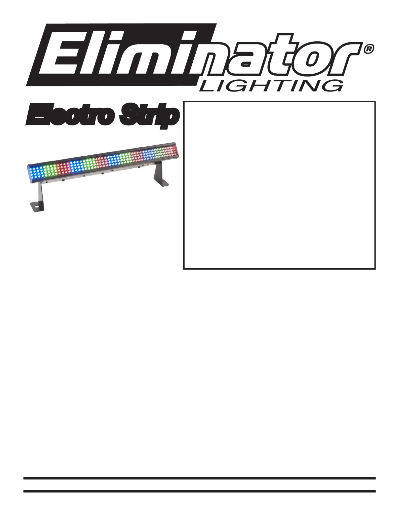
Electro Strip
SPECIFICATIONS:
Model: Electro Strip
LEDs: 192 - 64 Red, 64 Green,
& 64 Blue
Weight: 3.3lbs./ 1.5kgs.
Size: 19” (L) x 3.8” (W) x
5.1” (H)
Fuse: 2 Amp
Supply Voltage: 120V
Power Cord Daisy Chain: 33 Fixtures Max.
Working Position: Any Safe position
Duty Cycle: None
DMX Channels: 4
Colors: RGB
Warranty: 1 Year
CAUTION! Please read and
understand these instructions
before installing or operating
this unit.
Operating Instructions:
The Electro Strip has been tested at the factory, there is no assembly required. The unit is ready to
be plugged into a power outlet. This unit is a 4 channel DMX intelligent LED bar. This unit has 4 dif-
ferent operating modes; static color mode, chase mode, color change mode, and DMX controlled.
This unit can be run as a Stand Alone unit or in a Master/Slave configuration. For stand-alone mode,
and Master/Slave configuration settings, see other side.
Power Cord Daisy Chaining: With this feature you can connect the xtures to one another using the
IEC input and output sockets. The quantity that can be connected is 33 xtures maximum. After 33 x-
tures you will need to use a new power outlet. They must be the same xtures. DO NOT mix xtures.
©Eliminator® Los Angeles, CA. - www.EliminatorLighting.com
Caution! Never open unit when in use. Always disconnect main power before replacing fuse.
Remember to always replace with the exact same type fuse.
1 Year Limited Warranty:Eliminator Lighting warranty is valid from the date of purchase. Our
1 year limited warranty covers manufacturing defects only. Serial number, place of purchase with
dated valid receipt must be submitted at time of service. Eliminator Lighting warranty does not cover
items or parts prone to wear and tear: lamps, fuses, brushes and belts. Eliminator Lighting warranty
is only valid with-in the United States.
Produktspecifikationer
| Varumärke: | Eliminator Lighting |
| Kategori: | ej kategoriserat |
| Modell: | Electro Strip |
Behöver du hjälp?
Om du behöver hjälp med Eliminator Lighting Electro Strip ställ en fråga nedan och andra användare kommer att svara dig
ej kategoriserat Eliminator Lighting Manualer

13 Oktober 2025
12 Oktober 2025
12 Oktober 2025
12 Oktober 2025
12 Oktober 2025
12 Oktober 2025
20 Augusti 2025
19 Augusti 2025
19 Augusti 2025
19 Augusti 2025
ej kategoriserat Manualer
Nyaste ej kategoriserat Manualer
3 April 2026
3 April 2026
3 April 2026
3 April 2026
3 April 2026
3 April 2026
3 April 2026
3 April 2026
3 April 2026