Festo DADP-TU-F3-50 Bruksanvisning
Festo Inte kategoriserad DADP-TU-F3-50
Läs gratis den bruksanvisning för Festo DADP-TU-F3-50 (2 sidor) i kategorin Inte kategoriserad. Guiden har ansetts hjälpsam av 13 personer och har ett genomsnittsbetyg på 4.7 stjärnor baserat på 8 recensioner. Har du en fråga om Festo DADP-TU-F3-50 eller vill du ställa frågor till andra användare av produkten? Ställ en fråga
Sida 1/2
Translation of the original instructions
© 2021 all rights reserved to Festo SE & Co. KG
1Applicable documents
All available documents for the product www.festo.com/pk.è
DocumentProductContents
InstructionsStopper cylinder DFST-...-G2Operating
Tab. 1
2Safety
2.1Safety instructions
–Only mount the product on components that are in a condition to be safely
operated.
–Observe tightening torques. Unless otherwise specified, the tolerance
is±20%.
2.2Intended use
Control of toggle lever functions on stopper cylinder DFST-...-G2.
3Product overview
3.1Product Range Overview
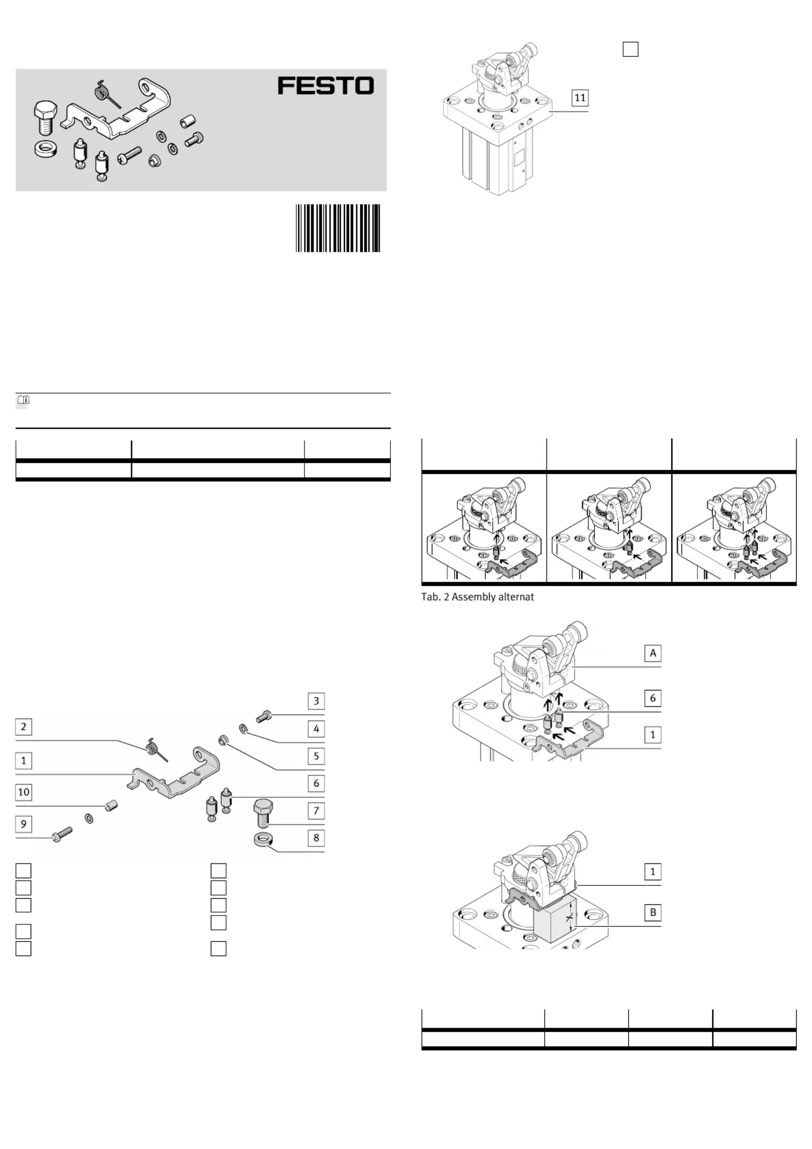
3.1.1Scope of delivery
1
Locking plate (1x)
2
Leg spring (1x)
3
Screw (1x)
M4x10
4
Split washer (2x)
5
Sleeve (1x)
6
Pin (2x)
7
Hexagon head screw (1x)
8
Washer (1x)
9
Screw (1x)
M4x15
10
Sleeve (1x)
Fig. 1
3.1.2Not in scope of delivery
11
Stopper cylinder (1x)
DFST-...-G2
Fig. 2
3.2Functions
Lever locking mechanism
This function fixes the toggle lever in the upper end position after it is pushed
through when stopping an object.
When the piston rod of the stopper cylinder is retracted, the toggle lever is
unlocked.
Lever deactivating mechanism
This function deactivates the stopping function after the toggle lever has been
manually pressed down.
When the piston rod of the stopper cylinder is retracted, the toggle lever is
unlocked.
4Mounting
4.1Assembly
The assembly alternatives for the pins determine the function.6
Lever locking mechan
ism
Lever deactivating mech
anism
Lever locking and lever
deactivating mechanism
Tab. 2 Assembly alternatives
Fig. 3 Positioning pins
1.Slide the pins into the corresponding slot for the locking plate.61
2.Position the pins in the clevis foot (A).6
Fig. 4 Fixing the locking plate
•Slide the block[B] under the locking plate.1
Ä
Pins are fixed.6
DADPTUF3506380
X[mm]303043
Tab. 3 Height of block[B]
8107268
DADPTUF350/63/80
Toggle lever function kit
8107268
2019-04
[8107270]
Instructions| Assembly
Festo SE & Co. KG
Ruiter Straße 82
73734 Esslingen
Germany
+49 711 347-0
www.festo.com
Produktspecifikationer
| Varumärke: | Festo |
| Kategori: | Inte kategoriserad |
| Modell: | DADP-TU-F3-50 |
Behöver du hjälp?
Om du behöver hjälp med Festo DADP-TU-F3-50 ställ en fråga nedan och andra användare kommer att svara dig
Inte kategoriserad Festo Manualer

30 Mars 2025
30 Mars 2025
30 Mars 2025
30 Mars 2025
30 Mars 2025
30 Mars 2025
30 Mars 2025
30 Mars 2025
30 Mars 2025
30 Mars 2025
Inte kategoriserad Manualer
Nyaste Inte kategoriserad Manualer
9 April 2025
9 April 2025
9 April 2025
9 April 2025
9 April 2025
9 April 2025
9 April 2025
9 April 2025
9 April 2025
9 April 2025