Festo SPTE-B2R-PC10-B-2.5K Bruksanvisning
Festo Inte kategoriserad SPTE-B2R-PC10-B-2.5K
Läs gratis den bruksanvisning för Festo SPTE-B2R-PC10-B-2.5K (2 sidor) i kategorin Inte kategoriserad. Guiden har ansetts hjälpsam av 18 personer och har ett genomsnittsbetyg på 4.8 stjärnor baserat på 4 recensioner. Har du en fråga om Festo SPTE-B2R-PC10-B-2.5K eller vill du ställa frågor till andra användare av produkten? Ställ en fråga
Sida 1/2
Pressure transmitter SPTE
Festo SE & Co. KG
Ruiter Straße 82
73734 Esslingen
Deutschland
+49 711 347-0
www.festo.com
Operating instructions
Original instructions
8058488
2017-03c
[8058490]
For all available product documentation è www.festo.com/pk
1Operating elements and connections
1
2
3
1Electrical connection
2Pneumatic connection
3Blanking plug
Fig. 1
FeatureSpecificationOrder code
FunctionSPTEPressure transmitter
Pressure measuring range-B2, -B11, -P025, -P05,
-P1, -P2, -P6, -P10,
-V025, -V05, -V1
èTechnical data
Pressure inputRRelative pressure
Mounting/pneumatic
connection
S4Push-in sleeve 4 mm (insertable)
S6Push-in sleeve 6 mm (insertable)
Q3Push-in connector 3 mm
Q4Push-in connector 4 mm
FFlange (with through-hole and screw)
PC10Cartridge 10 mm
Electrical outputB1 … 5 V
V0 … 10 V
Electrical connection2.5K2.5 m cable, open end
Fig. 2
2Function and application
The SPTE pressure transmitter is intended for measuring the relative pressure in
pneumatic applications. The SPTE converts pneumatic pressure values into an
electrical analogue signal, which can be used for control or regulating functions.
3Requirements for product use
Note
Incorrect handling can lead to malfunctioning.
These general conditions for the correct and safe use of the product must be
observed at all times.
Observe the specified limits, e.g. for pressures, forces, temperatures, etc.
(è 9 “Technical data”).
Ensure that there is a supply of correctly prepared compressed air.
Please observe the prevailing ambient conditions.
Please observe the regulations applicable to the place of use (e.g. those of local
or national institutions).
Remove all transport packing such as protective wax, foils, caps, cardboard
boxes.
Remove everything used for protection during transport such as protective wax,
films, caps and cardboard boxes. The individual materials can be stored in
containers for recycling purposes.
The device is intended for industrial use. Measures may need to be implemented
in residential areas for interference suppression.
Remove dirt particles in the supply lines by blowing through the tubing and
hoses. In this way you will protect the device from premature failure or heavy
wear (è DIN ISO 4414, section 9.4).
Please observe the warnings and instructions:
–on the product
–in these operating instructions.
3.1Range of application and certifications
The information in this section, in combination with the UL marking on the product,
must be observed in order for there to be compliance with the certification condi
tions of Underwriters Laboratories Inc. (UL) for USA and Canada. Observe the fol
lowing English-language remarks from UL:
For use only in or with complete equipment where the acceptability of the
combination is determined by UL LLC. When installed in an end-product,
consideration must be given to the following:
–This component has been judged on the basis of the creepage and clearances
required in the indicated standards, which would cover the component itself if
submitted for listing: UL 61010-1, CAN/CSA 22.2 No. 61010-1.
–The end-product shall consider that the enclosure does not serve as a
fire/electrical/mechanical enclosure, the product should be used with
enclosure at the end product.
–The output connectors are not investigated for field wiring.
–The unit is considered acceptable for use in a max ambient of: 50 °C/122 °F.
UL approval information
Product category codeQUYX2 (USA) or
QUXY8 (Canada)
File numberE322346
Considered StandardsUL 61010-1
CAN/CSA 22.2 No. 61010-1
UL mark
Fig. 3
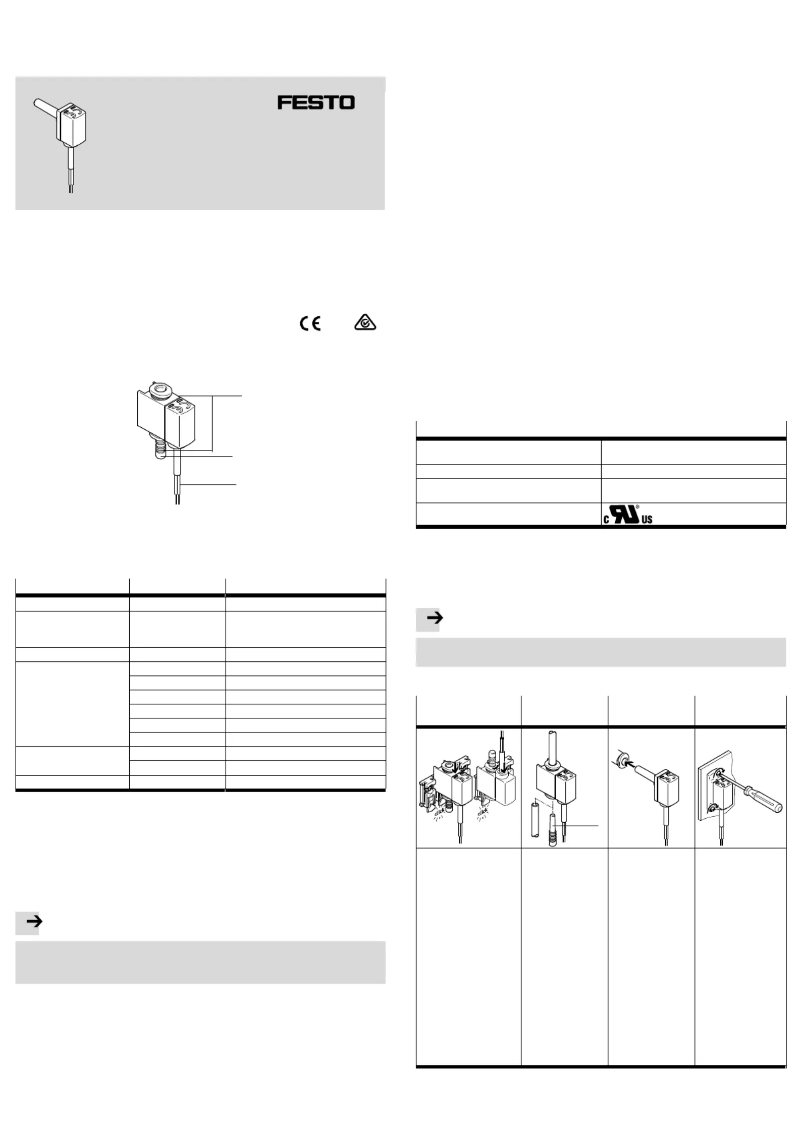
4Installation
4.1Mechanical and pneumatic
Note
Mount the SPTE or connect the tubing so that no condensation from the com
pressed air lines can gather in the device.
It can be fitted in any position. Mount the SPTE as follows:
SPTE-…-Q…
with mounting clip
SPTE-…-Q…SPTE-…-S…SPTE-…-F
1
1.If necessary, shorten
the SAMH-8 to the de
sired number of slots.
2.Observe the hole pat
tern for the SAMH
(èFig. 10).
3.Mount the SAMH with
M3 screws (included
in the scope of
delivery)
1)
.
4.Insert the SPTE into
the SAMH mounting
clip in the direction of
the arrow. (Cable
outlet at the top or
bottom is possible).
5.Connect the tubing of
the SPTE (ènext
column).
Single-ended tubing
1.Seal a pneumatic
connection on the
SPTE with the
blanking plug 1.
2.Connect the tube
to the free pneu
matic connection.
Double-sided tubing
1.Remove the
blanking plug 1.
2.Connect the tube
to both pneu
matic connec
tions.
1.Insert the
pneumatic
connection of the
SPTE into the
push-in fitting as
far as possible.
1.Observe the hole
pattern for the
flange (èFig. 10).
2.Check the correct
seating of the
sealing ring.
3.Secure the SPTE in
place using two M2
screws (included in
the scope of
delivery)
2)
.
1)Tightening torque: max. 0.6 Nm
2)Tightening torque: max. 0.3 Nm
Fig. 4
Produktspecifikationer
| Varumärke: | Festo |
| Kategori: | Inte kategoriserad |
| Modell: | SPTE-B2R-PC10-B-2.5K |
Behöver du hjälp?
Om du behöver hjälp med Festo SPTE-B2R-PC10-B-2.5K ställ en fråga nedan och andra användare kommer att svara dig
Inte kategoriserad Festo Manualer

30 Mars 2025
30 Mars 2025
30 Mars 2025
30 Mars 2025
30 Mars 2025
30 Mars 2025
30 Mars 2025
30 Mars 2025
30 Mars 2025
30 Mars 2025
Inte kategoriserad Manualer
Nyaste Inte kategoriserad Manualer
9 April 2025
9 April 2025
9 April 2025
9 April 2025
9 April 2025
9 April 2025
9 April 2025
9 April 2025
9 April 2025
9 April 2025