Generac QT06024KVSXR Bruksanvisning
Generac Generatorn QT06024KVSXR
Läs gratis den bruksanvisning för Generac QT06024KVSXR (80 sidor) i kategorin Generatorn. Guiden har ansetts hjälpsam av 18 personer och har ett genomsnittsbetyg på 4.6 stjärnor baserat på 5 recensioner. Har du en fråga om Generac QT06024KVSXR eller vill du ställa frågor till andra användare av produkten? Ställ en fråga
Sida 1/80
This manual should remain with the unit.
2.4L
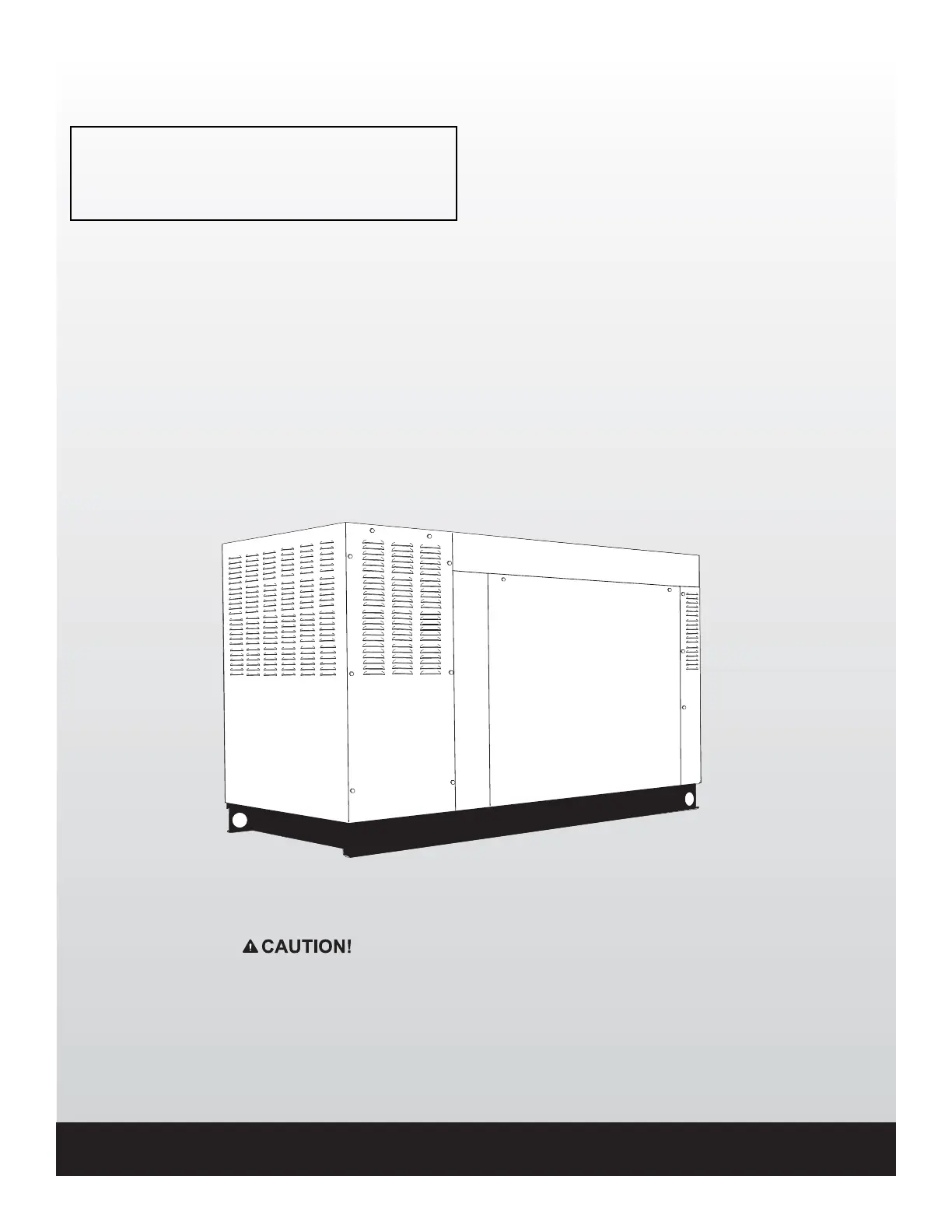
60kW Models
EPA Certified
Owner's Manual
Stationary Emergency Generator
Cover213 Rev. A 03/12Part No. 0J8648
NOT INTENDED FOR USE IN CRITICAL LIFE SUPPORT
APPLICATIONS.
ONLY QUALIFIED ELECTRICIANS OR CONTRACTORS
SHOULD ATTEMPT INSTALLATION!
DEADLY EXHAUST FUMES! OUTDOOR INSTALLATION
ONLY!
Produktspecifikationer
| Varumärke: | Generac |
| Kategori: | Generatorn |
| Modell: | QT06024KVSXR |
Behöver du hjälp?
Om du behöver hjälp med Generac QT06024KVSXR ställ en fråga nedan och andra användare kommer att svara dig
Generatorn Generac Manualer

22 Oktober 2024
20 Oktober 2024
19 Oktober 2024
19 Oktober 2024
19 Oktober 2024
18 Oktober 2024
17 Oktober 2024
16 Oktober 2024
14 Oktober 2024
14 Oktober 2024
Generatorn Manualer
Nyaste Generatorn Manualer
25 Januari 2025
9 Januari 2025
21 Oktober 2024
14 Oktober 2024
12 Oktober 2024
8 Oktober 2024
31 Juli 2024
31 Juli 2024
31 Juli 2024
29 Juli 2024