Generac QT08046JNAN Bruksanvisning
Generac
Inte kategoriserad
QT08046JNAN
Läs gratis den bruksanvisning för Generac QT08046JNAN (136 sidor) i kategorin Inte kategoriserad. Guiden har ansetts hjälpsam av 5 personer och har ett genomsnittsbetyg på 4.8 stjärnor baserat på 3 recensioner. Har du en fråga om Generac QT08046JNAN eller vill du ställa frågor till andra användare av produkten? Ställ en fråga
Sida 1/136

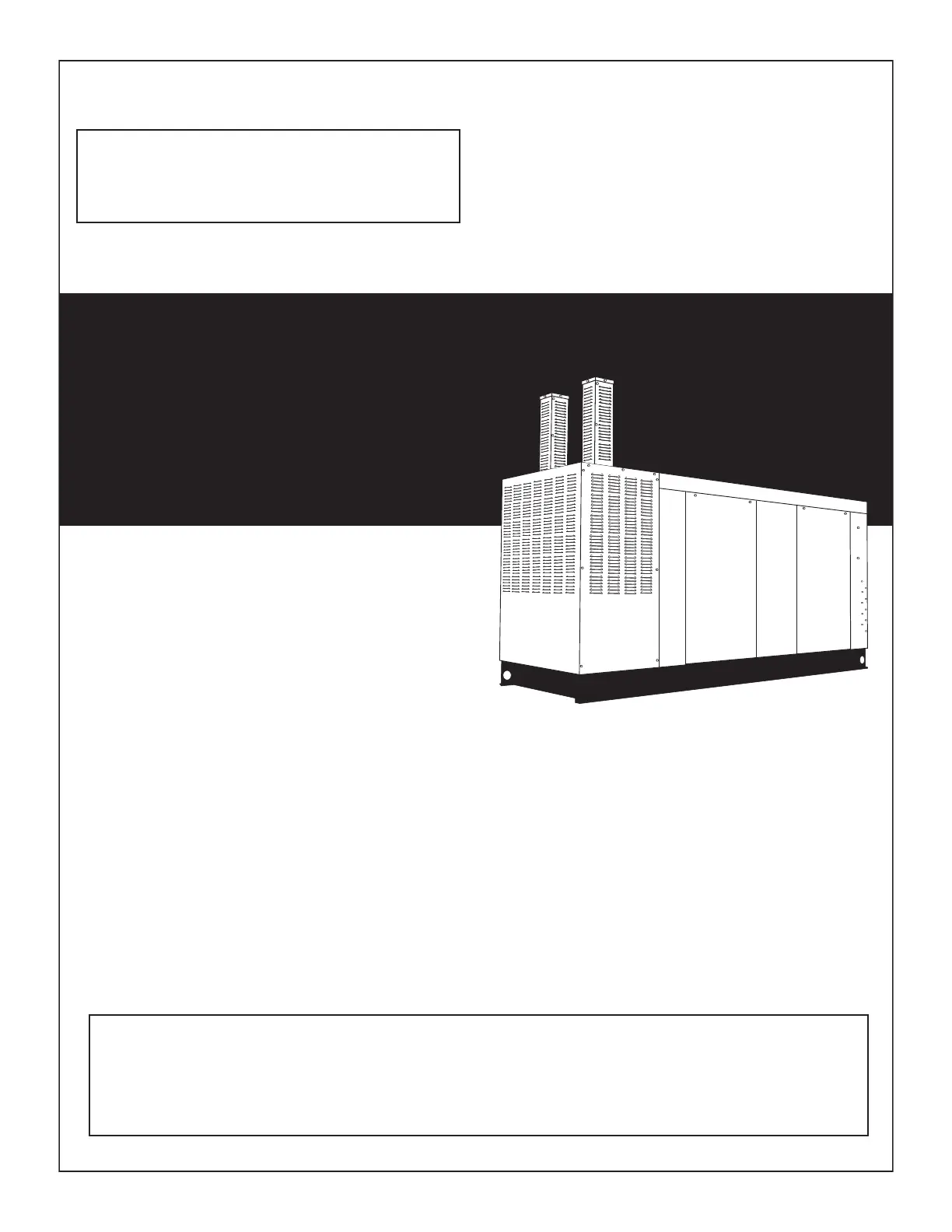
STATIONARY EMERGENCY GENERATOR
OWNER'S MANUAL
This manual should remain with the unit.
A new standard of reliability
Serial Number
4.6L
80kW
Models
EPA Certified
Not intended for use in critical life support applications.
ONLY QUALIFIED ELECTRICIANS OR CONTRACTORS SHOULD ATTEMPT INSTALLATION!
DEADLY EXHAUST FUMES. OUTDOOR INSTALLATION ONLY!
—CAUTION—
Cover184 Rev. A 08/09 Part No. 0H3916

Stationary Emergency Generator
Table of Contents
SECTION PAGE
SAFETY RULES ............................................................. 1-1
INTRODUCTION ............................................................................... 1-3
Read this Manual Thoroughly .......................................................1-3
Operation and Maintenance ..........................................................1-3
How to Obtain Service .................................................................1-3
IDENTIFICATION RECORD ...............................................................2-1
Data Label ...................................................................................2-1
EQUIPMENT DESCRIPTION .............................................................3-1
Equipment Description .....................................................................3-1
Engine Oil Recommendations ...........................................................3-1
Coolant Recommendations ..............................................................3-1
ENGINE PROTECTIVE DEVICES .......................................................4-1
Coolant Temperature Sensing .......................................................4-1
Low Coolant Level .......................................................................4-1
Oil Pressure Sensing ....................................................................4-1
Overcrank Shutdown ....................................................................4-1
Overspeed Shutdown ...................................................................4-1
RPM Sensor Loss Shutdown........................................................4-1
DC Fuse .......................................................................................4-1
FUEL SYSTEMS ..............................................................................5-1
Fuel Requirements .......................................................................5-1
Natural Gas Fuel System ..............................................................5-1
Propane Vapor Withdrawal Fuel System ........................................5-1
LP Fuel System ............................................................................5-1
SPECIFICATIONS .............................................................................6-1
Generator .....................................................................................6-1
Engine .........................................................................................6-1
Cooling System............................................................................6-1
Fuel System .................................................................................6-1
Electrical System .........................................................................6-1
Weather and Maintenance Kits .....................................................6-2
4.6L Ignition Description ..................................................................6-2
Ignition Shutdown on Loss of Crank or CAM Signals ....................6-2
Diagnostic Blink Patterns (Red LED Located
on the Ignition Control Board ........................................................6-2
GENERAL INFORMATION.................................................................7-1
Generator AC Lead Connections .......................................................7-1
Four-lead, Single-phase Stator ......................................................7-1
Alternator Power Winding Connections .............................................7-1
3-phase Alternators ......................................................................7-1
INSTALLATION ................................................................................8-1
Installation .......................................................................................8-1
Preparation Before Start-up ..............................................................8-1
Transfer Switch ............................................................................8-1
Fuel System .................................................................................8-1
Generator Set Lubrication .............................................................8-1
Prior to Initial Start-up ..................................................................8-1
Initial Inspection for QT Genset Start-up ...........................................8-2
Start-up Inspection ......................................................................8-2
OPERATION ..................................................................................... 9-1
Generator Control and Operation ......................................................9-1
Operating Unit with Automatic Transfer Switch .................................9-1
Operating Unit with Manual Transfer Switch ......................................9-1
Engine Start-up and Transfer ........................................................9-1
Retransfer and Shutdown .............................................................9-1
MAINTENANCE .............................................................................. 10-1
Maintenance Performed by Authorized
Service Facilities .........................................................................10-1
Cooling System..............................................................................10-1
Checking Fluid Levels .....................................................................10-1
Check Engine Oil ........................................................................10-1
Battery Fluid ...............................................................................10-1
Engine Coolant ...........................................................................10-2
Maintenance Owner/Operator Can Perform .....................................10-2
Check Engine Oil Level ...............................................................10-2
Check Battery ............................................................................10-2
Exercise System ........................................................................10-2
Inspect Cooling System .............................................................10-2
Check Engine Coolant Level .......................................................10-2
Perform Visual Inspection ..........................................................10-2
Inspect Exhaust System .............................................................10-2
Check Fan Belt ...........................................................................10-2
Inspect Engine Governor ............................................................10-2
Changing Engine Oil ...................................................................10-2
Changing the Engine Air Cleaner.................................................10-3
Spark Plugs ...............................................................................10-3
Coolant Change .........................................................................10-3
Miscellaneous Maintenance ...........................................................10-3
Cleaning the Generator ...............................................................10-3
Battery .......................................................................................10-4
Battery Maintenance ..................................................................10-4
Battery Replacement ..................................................................10-4
SERVICE SCHEDULE .....................................................................11-1
30 kW - 150 kW Standby Gas Engine
Driven Generator Sets .................................................................11-1
TROUBLESHOOTING .....................................................................12-1
Troubleshooting Guide ....................................................................12-1
EMISSIONS WARRANTY ...............................................................13-1
NOTES
EXPLODED VIEWS & PARTS LISTS
WIRING DIAGRAMS & SCHEMATICS
Content025 Rev. C 02/10

INTRODUCTION
Thank you for purchasing this model of the stationary emergency
generator product line.
Every effort was expended to make sure that the information and
instructions in this manual were both accurate and current at the
time the manual was written. However, the manufacturer reserves
the right to change, alter or otherwise improve this product(s) at
any time without prior notice.
READ THIS MANUAL THOROUGHLY
If any portion of this manual is not understood, contact the nearest
Service Dealer for starting, operating and servicing procedures.
Throughout this publication, and on tags and decals affixed to the
generator, DANGER, WARNING, CAUTION and NOTE blocks are
used to alert personnel to special instructions about a particular
service or operation that may be hazardous if performed incor-
rectly or carelessly. Observe them carefully. Their definitions are
as follows:
INDICATES A HAZARDOUS SITUATION OR ACTION WHICH, IF
NOT AVOIDED, WILL RESULT IN DEATH OR SERIOUS INJURY.
Indicates a hazardous situation or action which, if not
avoided, could result in death or serious injury.
Indicates a hazardous situation or action which, if not
avoided, could result in minor or moderate injury.
NOTE:
Notes contain additional information important to a procedure
and will be found within the regular text body of this manual.
These safety warnings cannot eliminate the hazards that they
indicate. Common sense and strict compliance with the special
instructions while performing the service are essential to prevent-
ing accidents.
Four commonly used safety symbols accompany the DANGER,
WARNING and CAUTION blocks. The type of information each
indicates is as follows:
n
This symbol points out important safety information that,
if not followed, could endanger personal safety and/or
property of others.
This symbol points out potential explosion hazard.
This symbol points out potential fire hazard.
This symbol points out potential electrical shock hazard.
The operator is responsible for proper and safe use of the equip-
ment. The manufacturer strongly recommends that the operator
read this Owner's Manual and thoroughly understand all instruc-
tions before using this equipment. The manufacturer also strongly
recommends instructing other users to properly start and operate
the unit. This prepares them if they need to operate the equipment
in an emergency.
For safety reasons, the manufacturer recommends that this
equipment be installed, serviced and repaired by a Service
Dealer or other competent, qualified electrician or installation
technician who is familiar with applicable codes, standards and
regulations. The operator also must comply with all such codes,
standards and regulations.
OPERATION AND MAINTENANCE
It is the operator's responsibility to perform all safety checks, to
make sure that all maintenance for safe operation is performed
promptly, and to have the equipment checked periodically by a
Service Dealer. Normal maintenance service and replacement of
parts are the responsibility of the owner/operator and, as such,
are not considered defects in materials or workmanship within the
terms of the warranty. Individual operating habits and usage con-
tribute to the need for maintenance service.
Proper maintenance and care of the generator ensure a minimum
number of problems and keep operating expenses at a minimum.
See a Service Dealer for service aids and accessories.
Operating instructions presented in this manual assume that the
generator electric system has been installed by a Service Dealer or
other competent, qualified contractor. Installation of this equipment
is not a “do-it-yourself” project.
HOW TO OBTAIN SERVICE
When the generator requires servicing or repairs, simply contact
a Service Dealer for assistance. Service technicians are factory-
trained and are capable of handling all service needs.
When contacting a dealer about parts and service, always supply
the complete Model Number, Serial Number and Type Code (where
applicable) from the DATA LABEL that is affixed to the unit.
1-1
Safety004 Rev. F 05/10
Safety Instructions
n
SAVE THESE INSTRUCTIONS – The manufacturer suggests that these rules for safe operation be copied and posted in potential
hazard areas. Safety should be stressed to all operators, potential operators, and service and repair technicians for this
equipment.
Produktspecifikationer
Varumärke: | Generac |
Kategori: | Inte kategoriserad |
Modell: | QT08046JNAN |
Färg på produkten: | Black, Blue |
Vikt: | 195 g |
Bredd: | 77 mm |
Djup: | 26 mm |
Höjd: | 111 mm |
Husmaterial: | Aluminium |
Processorfrekvens: | 0.192 GHz |
Processorfamilj: | ARM9 |
Inkluderar operativsystem: | Linux |
Ethernet LAN: | Ja |
Kompatibla minneskort: | SD |
Mikrofon, linjeingång: | Nee |
DVI-port: | Nee |
Antal Ethernet LAN (RJ-45)-portar: | 1 |
Certifiering: | EMC:\nFCC: Part 15, Part 24/24\nCE: EN55022, EN61000\nR&TTE: EN301 489-1, EN301 489-7, EN301 511\nSafety: \nLVD: EN60950-1\nUL/cUL: UL60950-1, CSA C22.2 No. 60950-1-03\n\nDirectives: GCF-CC, RoHS, CRoHS, WEEE |
Internminne: | 0.032 GB |
Förvarings media: | Flash |
Hållbarhetscertifikat: | RoHS |
Ethernet LAN, dataöverföringshastigheter: | 10, 100 Mbit/s |
Kabelteknik: | 10/100Base-T(X) |
Förvaringstemperatur: | -20 - 80 °C |
Maximalt internminne: | - GB |
Total lagringskapacitet: | 0.016 GB |
Typ av optisk enhet: | Nee |
Diskret grafikadaptermodell: | Niet beschikbaar |
Inkluderar monitor: | Nee |
Seriell port(ar): | 1 |
Strömförsörjning, spänningsingång: | 12 - 48 V |
Drifttemperatur (TT): | -10 - 60 °C |
Relativ luftfuktighet i drift (VV): | 5 - 95 procent |
Typ produkt: | Ingebouwde pc |
Behöver du hjälp?
Om du behöver hjälp med Generac QT08046JNAN ställ en fråga nedan och andra användare kommer att svara dig
Inte kategoriserad Generac Manualer
27 Oktober 2024
27 Oktober 2024
27 Oktober 2024
26 September 2024
26 September 2024
26 September 2024
7 September 2024
6 September 2024
5 September 2024
5 September 2024
Inte kategoriserad Manualer
- PeakTech
- Leifheit
- Davita
- Oregon Scientific
- Enhance
- Dwarf Connection
- Arlec
- Tumbleweed
- Doomoo
- Laserliner
- Hoover
- Sonel
- Rug Doctor
- Hagor
- Blade
Nyaste Inte kategoriserad Manualer
9 April 2025
9 April 2025
9 April 2025
9 April 2025
9 April 2025
9 April 2025
9 April 2025
9 April 2025
9 April 2025
9 April 2025