Generac QT08054KVNNA Bruksanvisning
Läs gratis den bruksanvisning för Generac QT08054KVNNA (144 sidor) i kategorin Generator. Guiden har ansetts hjälpsam av 17 personer och har ett genomsnittsbetyg på 4.0 stjärnor baserat på 7 recensioner. Har du en fråga om Generac QT08054KVNNA eller vill du ställa frågor till andra användare av produkten? Ställ en fråga
Sida 1/144
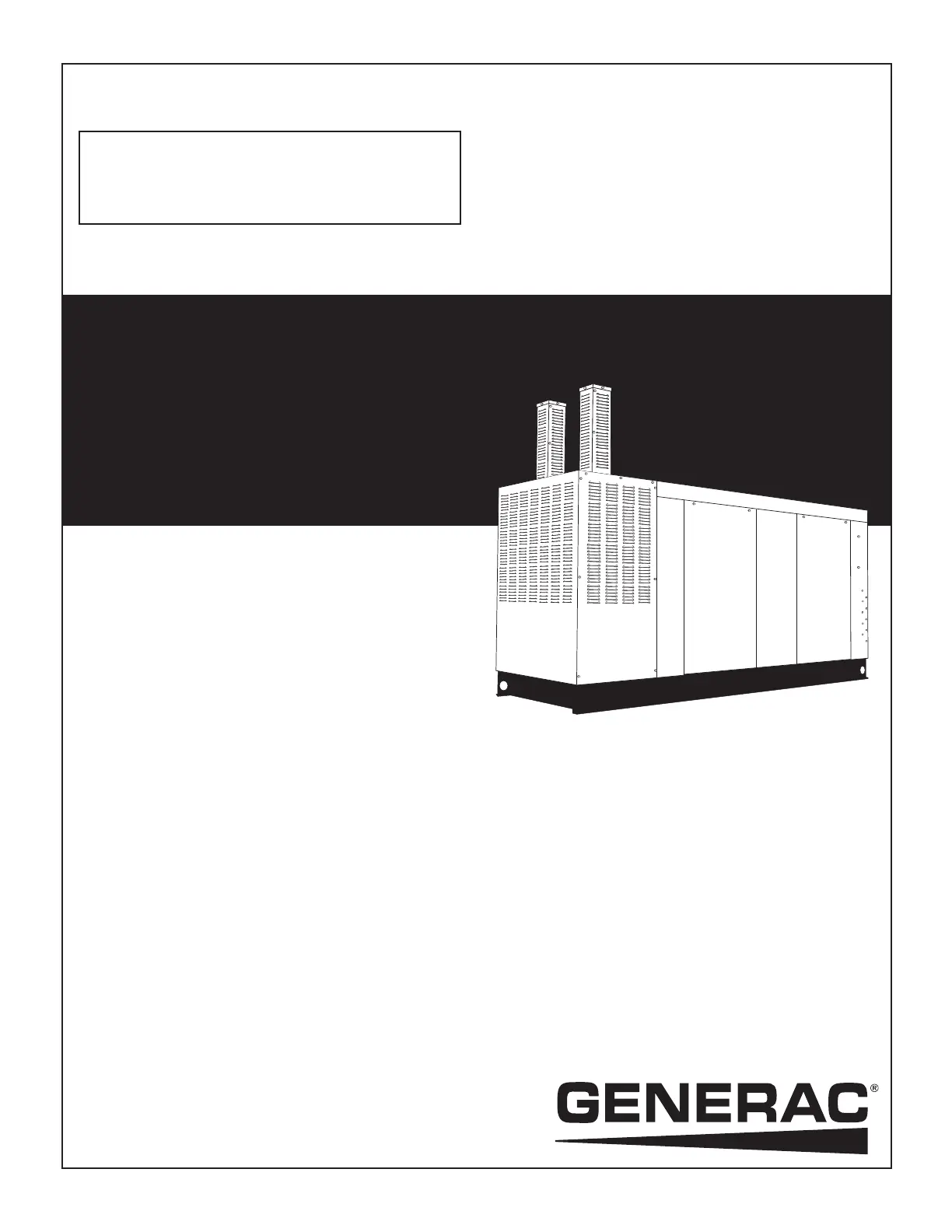
STATIONARY EMERGENCY GENERATOR
OWNER'S MANUAL
This manual should remain with the unit.
Serial Number
Industrial QT
5.4L
80kW
Models
A new standard of reliability
Cover049 Rev. A 03/09
Part No. 0G1215
Produktspecifikationer
| Varumärke: | Generac |
| Kategori: | Generator |
| Modell: | QT08054KVNNA |
Behöver du hjälp?
Om du behöver hjälp med Generac QT08054KVNNA ställ en fråga nedan och andra användare kommer att svara dig
Generator Generac Manualer

19 Augusti 2025
14 Augusti 2025
14 Augusti 2025
14 Augusti 2025
14 Augusti 2025
14 Augusti 2025
14 Augusti 2025
13 Augusti 2025
13 Augusti 2025
13 Augusti 2025
Generator Manualer
Nyaste Generator Manualer
15 Mars 2026
3 Februari 2026
1 Februari 2026
31 Januari 2026
28 Januari 2026
27 Januari 2026
27 Januari 2026
25 Januari 2026
21 Oktober 2025
15 Oktober 2025