Generac QT15068GVNNA Bruksanvisning
Generac Inte kategoriserad QT15068GVNNA
Läs gratis den bruksanvisning för Generac QT15068GVNNA (146 sidor) i kategorin Inte kategoriserad. Guiden har ansetts hjälpsam av 17 personer och har ett genomsnittsbetyg på 4.3 stjärnor baserat på 5 recensioner. Har du en fråga om Generac QT15068GVNNA eller vill du ställa frågor till andra användare av produkten? Ställ en fråga
Sida 1/146
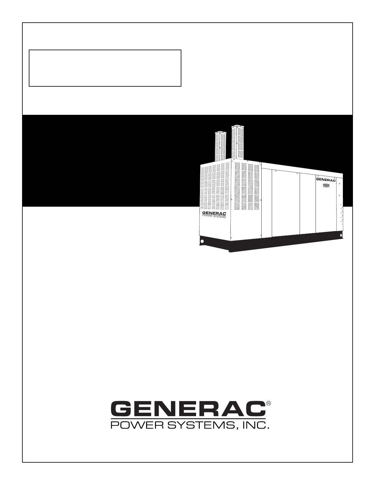
STANDBY GENERATOR
OWNER'S MANUAL
This manual should remain with the unit.
A new standard of reliability
Serial Number
Industrial QT
6.8L
150kW
Models
Cover073 Rev. 0 05/06Part No. 0G2034
Produktspecifikationer
| Varumärke: | Generac |
| Kategori: | Inte kategoriserad |
| Modell: | QT15068GVNNA |
Behöver du hjälp?
Om du behöver hjälp med Generac QT15068GVNNA ställ en fråga nedan och andra användare kommer att svara dig
Inte kategoriserad Generac Manualer

27 Oktober 2024
27 Oktober 2024
27 Oktober 2024
26 September 2024
26 September 2024
26 September 2024
7 September 2024
6 September 2024
5 September 2024
5 September 2024
Inte kategoriserad Manualer
Nyaste Inte kategoriserad Manualer
9 April 2025
9 April 2025
9 April 2025
9 April 2025
9 April 2025
9 April 2025
9 April 2025
9 April 2025
9 April 2025
9 April 2025