Grundfos Alpha2 L Bruksanvisning
Läs gratis den bruksanvisning för Grundfos Alpha2 L (22 sidor) i kategorin Pomp. Guiden har ansetts hjälpsam av 36 personer och har ett genomsnittsbetyg på 4.7 stjärnor baserat på 6 recensioner. Har du en fråga om Grundfos Alpha2 L eller vill du ställa frågor till andra användare av produkten? Ställ en fråga
Sida 1/22
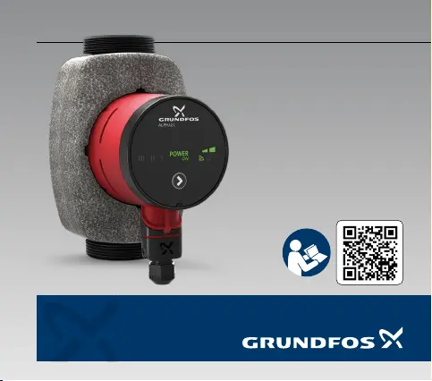
GRUNDFOSINSTRUCTIONS
ALPHA2 L
Model C
Produktspecifikationer
| Varumärke: | Grundfos |
| Kategori: | Pomp |
| Modell: | Alpha2 L |
Behöver du hjälp?
Om du behöver hjälp med Grundfos Alpha2 L ställ en fråga nedan och andra användare kommer att svara dig
Pomp Grundfos Manualer

1 April 2025
1 April 2025
1 April 2025
1 April 2025
1 April 2025
1 April 2025
1 April 2025
1 April 2025
1 April 2025
1 April 2025
Pomp Manualer
Nyaste Pomp Manualer
5 April 2025
1 April 2025
1 April 2025
30 Mars 2025
30 Mars 2025
30 Mars 2025
30 Mars 2025
29 Mars 2025
29 Mars 2025
29 Mars 2025