Hager 85245285 Bruksanvisning
Hager Inte kategoriserad 85245285
Läs gratis den bruksanvisning för Hager 85245285 (3 sidor) i kategorin Inte kategoriserad. Guiden har ansetts hjälpsam av 13 personer och har ett genomsnittsbetyg på 4.4 stjärnor baserat på 3 recensioner. Har du en fråga om Hager 85245285 eller vill du ställa frågor till andra användare av produkten? Ställ en fråga
Sida 1/3
Radio shutter push-button
quicklink
Safety instructions
Electrical equipment must only be installed and
assembled by a qualied electrician in ac-
cordance with the relevant installation stan-
dards, regulations, directives and safety and ac-
cident prevention directives of the country.
Failure to comply with these instructions may
result in damage to the device, re, or other ha-
zards.
The radio transmission is not suitable for safety
or alarm applications.
These instructions are an integral component of
the product, and must be retained by the end
user.
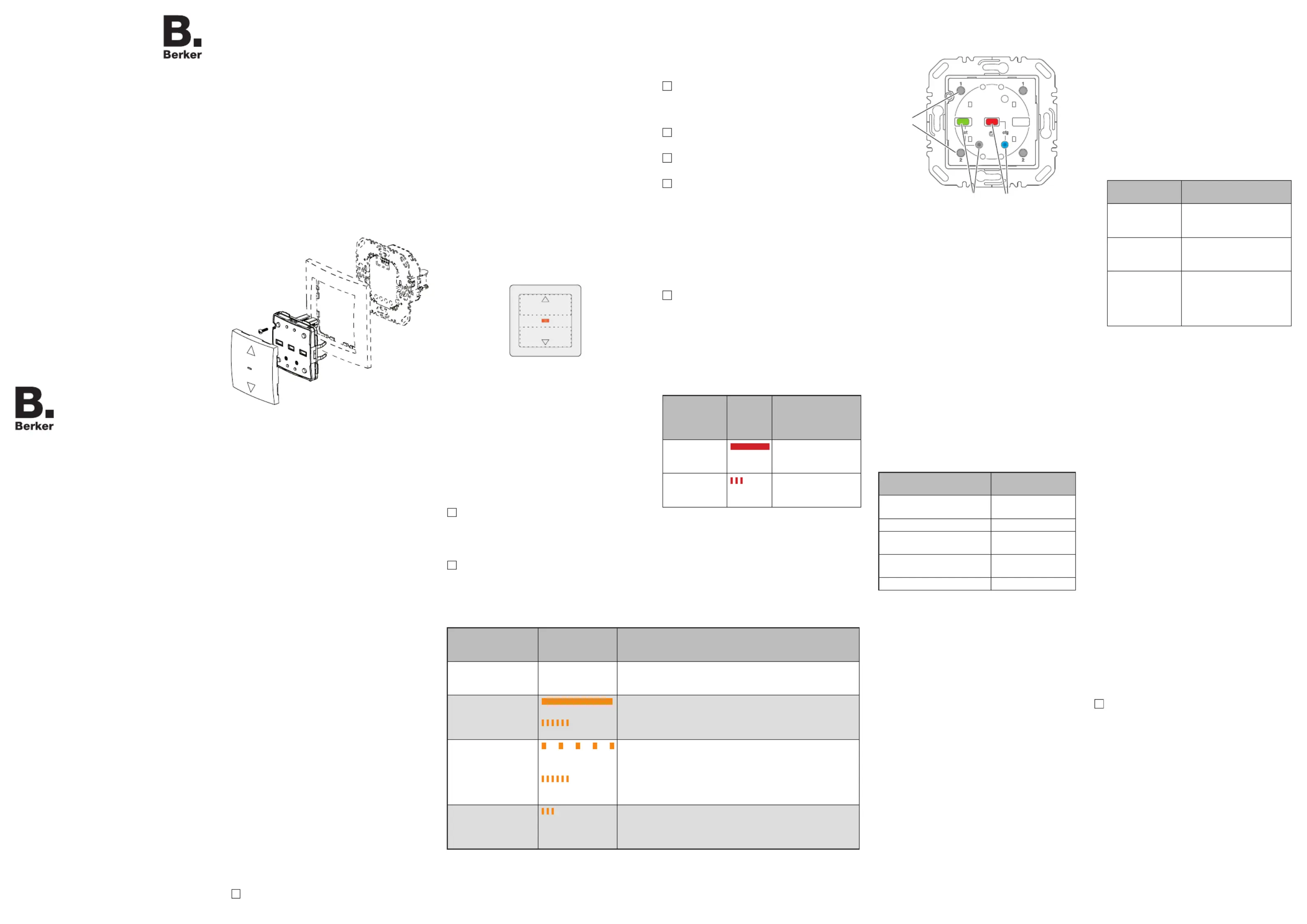
Design of the device
(3)
(4)
(7)
(5)
(6)
(2)
(1)
(1) Insert (see Accessories, not in scope of
delivery)
(2) Plug interface
(3) Frame (not in scope of delivery)
(4) Application module
(5) Push-button design cover
(6) Status LED
(7) Screw for dismantling protection
(not for design lines R.1/R.3)
Function
System information
This device is a product of the quicklink system, in
which installation devices communicate via radio
signals.
quicklink stands for a conguration mode in which
the function-related connection between transmit-
ters and receivers is set on the device via push-
buttons and displays without further tools.
All devices congurable via quicklink can be ope-
rated together in one system.
This device is compliant to the R&TTE-Directive
1999/5/EG. The Declaration of Conformity and
further system information can be found on our
homepage www.berker.de.
The device may be used in all EU and EFTA
countries.
Correct use
-Application module for blind inserts or power
supply for radio application module
-Manual and automatic operation of blind/shut-
ter motors connected to insert
-Transmission and reception of manual, time-
controlled and automatic operation commands
via quicklink
-Unsuitable for lighting control
-Only suitable for use in indoor areas, no drip or
spray water
The quicklink con guration of the devices must
only be carried out by qualied electricians.
Press both push-
button operation
areas
Status LED
display
Function and LED display
0 ... 5 sRunning/recording of memory function is nished, the Status
LED goes out and the radio blind push-button changes to
normal operation.
5 ... 10 s until the
Status LED ashes
orange for the rst
time
Memory function is executed, the LED is on.
The Status LED ashes for 3 s: memory is empty and the
radio blind push-button returns to normal operation.
10 ... 15 s until the
Status LED ashes
orange for the
second time
Memory function operation times are recorded, the Status
LED ashes orange for 2 s.
Memory is full. Only 10 operation times can be recorded.
The radio blind push-button changes back to normal opera-
tion.
15 ... 20 s until the
Status LED ashes
orange for the third
time
The Status LED ashes for 3 s: memory function is deleted
and the radio shutter push-button changes to normal ope-
ration.
Table 1: Operation of memory function
Product characteristics
-quicklink functions for integration into the remo-
te and group control of blinds/shutters
-Integration into scenes
-Party function to prevent unintentional operati-
on of roller shutters through automated operati-
on commands as well as radio/extension unit
commands
-Memory function for easy time control of con-
nected shutters
-Brightness-dependent operation when using a
radio sun sensor
-LED display of insert/application module com-
patibility
Operation
Operating concept
The operation of the top or bottom push-button
operation area is validated differently for each
button. Simultanous pressing of both push-button
operation areas on a blind insert controls special
functions such as memory or party function.
(8)
(9)
(10)
Figure 2: Operating element
(8) Push-button operation area for UP
(9) Status LED
(10) Push-button operation area for DOWN
Operation on a blind insert and power supply
for radio application module
Press push-button operation area or .
Short-press (shorter than 0.4 s): jog mode and
adjustment of slat positions.
Long-press: lock, shutter moves to nal
position.
Maximum run time in lock-time is 2 minutes.
Short press on push-button operation area
or during the shutter movement.
The shutter stops at the position reached.
If a protection signal (wind, rain) is present, no
move commands are executed (see Setting
Operating Mode).
Memory function
Operation times (if additionally required, also with
stop time for blind positions) can be recorded
for a 24-hour interval on blind inserts using the
memory function. Saved local and extension unit
operations> 0.4 s are hence executed daily and
automatically (For operation, see Table 1).
After a power failure, motion and stop com-
mands falling into that power failure period are
not executed with a time delay after voltage
recovery.
The memory function cannot be used when the
party function is active.
A maximum of 10 actions can be recorded for
the 24-hour interval.
The memory function is not available for opera-
tion on a power supply for radio application
modules.
Party function
The party function prevents unintentional operati-
on of the controlled blinds/shutters by the memory
function or extension unit operation, e.g. to pre-
vent persons from being shut out by the shutter
moving down.
When the Party function is active, a blind/shut-
ter can only be operated manually using the
buttons. Control of the shutter by higher-level
control-sections and sensors as well as by ex-
tension units or radio commands is deactiva-
ted. If the blind/shutter was moved to a dened
position in forced mode (see Table 4) and if this
forced mode is active, then the Party function
cannot be selected.
Press both
push-button
operation
areas
Status
LED
display
Function and LED
display
> 20 s until the
Status LED
turns red
Party function is
activated, the Status
LED turns red
> 20 s until the
Status LED
ashes red 3 x
Party function deac-
tivated, the Status
LED ashes red 3 x
Table 2: Operation of party function
Information for electricians
Overview of the operating elements beneath
the design cover
(13)
(12)
(11)
Figure 3: Operating elements for radio congurati-
on
(11) Press-activation points of the push-button
operation areas
(12) fct button and fct LED
(13) cfg button and cfg LED
Mounting
Selecting mounting location
A minimum distance between the transmitter and
corresponding receiver of about 1 m must be
maintained.
A minimum distance to electronic devices which
emit high frequency signals such as computers,
electronic transformers or microwave devices of
approx. 0.5 m must be maintained.
Mounting on or close to metal surfaces may cause
impairment ofthe radio transmission.
Take material penetration into account. The range
of the system can be optimised by selecting the
best possible mounting location:
Materiale MaterialDegree of material
penetration
Wood, plaster, plaster-
board, uncoated glass
approx. 90%
Brick, press boardsapprox. 70 %
Reinforced concrete, oor
heating
approx. 30 %
Metal, metal grids, alumini-
um laminates, coated glass
approx. 10 %
Rain, snowapprox. 1 ... 40 %
Table 3: degree of material penetration
Assembly of the device (Figure 1)
The insert is installed (see operating instructions
for the insert).
Attach application module (4) together with
frame (3) to a suitable shutter insert (see Ac-
cessories) so that the contact pins are inserted
into the available jack (2).
As soon as voltage is supplied to the radio
shutter push-button, the cfg LED (Figure 3, 13)
indicates whether the radio shutter push-button
and the insert are compatible with each other.
In the meantime, the operating mode can be
changed if necessary (see Setting Operating
Mode).
Display LED cfg
cfg LED display
Signicato Meaning
cfg LED ashes
green for 5 s
Compatible
cfg LED ashes
red for 5 s
Not compatible
LED blinks oran-
ge for 5 s
Compatible, but not con
gured to each other. For a
new con guration, the ap-
plication module must be
reset to factory settings.
If available, x dismantling protection with
screw (7).
After conguration, click the design cover (6)
into place on the application module (2).
Setting Operating Mode
It is possible to change between two operating
modes during commissioning:
- Protection Mode (factory setting):
Mode for using sensors on the extension unit
inputs of the insert to protect against wind or
rain damage on outside blinds/awnings.
In protection mode no move commands are
executed while a signal (wind /rain sensor) is
present on the extension unit input.
- Manual Mode:
The last move command is executed regard-
less of whether or not it takes place locally or
via an extension unit.
The application module was attached to the
insert, the insert/application module detection is
executed.
While the LED (6) is ashing green, hold the
push-button operation area and simulta-
neously for approx. 5 s until the LED ashes
orange.
The operating mode is changed and displayed:
The LED ashes 2x. The protection mode is
set.
or:
The LED ashes 1x. The manual mode is set.
In normal operation, the operating mode can-
not be displayed.
Radio shutter push-button
quicklink
Nr.ord.: 8524 52 ..
Operation and
installation instructions
Berker GmbH & Co. KG
Klagebach 38
58579 Schalksmühle/Germany
Telefon: + 49 (0) 23 55/90 5-0
Telefax: + 49 (0) 23 55/90 5-111
www.berker.com
11/2016
6LE001962B
z
z
Produktspecifikationer
| Varumärke: | Hager |
| Kategori: | Inte kategoriserad |
| Modell: | 85245285 |
Behöver du hjälp?
Om du behöver hjälp med Hager 85245285 ställ en fråga nedan och andra användare kommer att svara dig
Inte kategoriserad Hager Manualer

2 April 2025
2 April 2025
2 April 2025
2 April 2025
2 April 2025
2 April 2025
2 April 2025
2 April 2025
2 April 2025
1 April 2025
Inte kategoriserad Manualer
Nyaste Inte kategoriserad Manualer
9 April 2025
9 April 2025
9 April 2025
9 April 2025
9 April 2025
9 April 2025
9 April 2025
9 April 2025
9 April 2025
9 April 2025