Hager RED112X Bruksanvisning
Hager Inte kategoriserad RED112X
Läs gratis den bruksanvisning för Hager RED112X (3 sidor) i kategorin Inte kategoriserad. Guiden har ansetts hjälpsam av 14 personer och har ett genomsnittsbetyg på 5.0 stjärnor baserat på 6 recensioner. Har du en fråga om Hager RED112X eller vill du ställa frågor till andra användare av produkten? Ställ en fråga
Sida 1/3
0102
RED112X
Switching relay 1gang with input
RMD i2 audio light grey
§
ba
312
+
~
-
~
-
0
+
12
3
4
NC
C
NO
ab
i2-Bus
Adr.
+
~
-
~
Time
Control
DIP-
Switch
in
max.24V/1A
-
0
+
12
3
4
RED112X
6LE001405B
Tehalit GmbH, Seebergstraße 37, 67716 Heltersberg, Germany +49 6333 992 0 +49 6333 992 7666 info@hager.com hager.com - 03.2023TF
Safety instructions
Electrical equipment may only be installed and
assembled by qualifi ed electricians.
Failure to comply with these instructions may
result in damage to the device, fi re or other
hazards.
When installing and laying cables, always com-
ply with the applicable regulations and stand-
ards for SELV electrical circuits.
These instructions are an integral component
of the product and must be retained by the end
user.
Function
The RED112X allows switching and control func-
tions for the BUS. The switching relay has a poten-
tial-free change-over contact that can be used for
different switching functions.
The state of the relay and "Control-In" control input
is signalled via the corresponding LEDs.
CAUTION!
The switching relay is an i2Audio
device and can only be operated on
the 2-wire bus with an audio decou-
pler.
ç
Design and layout of the device
ba
312
+
~
-
~
-
0
+
12
3
4
NC
C
NO
ab
i2-Bus
Adr.
+
~
-
~
Time
Control
DIP-
Switch
in
max.24V/1A
-
0
+
12
3
4
RED112X
(1)(2)(3)
(4)(7)(6)(5)(8)
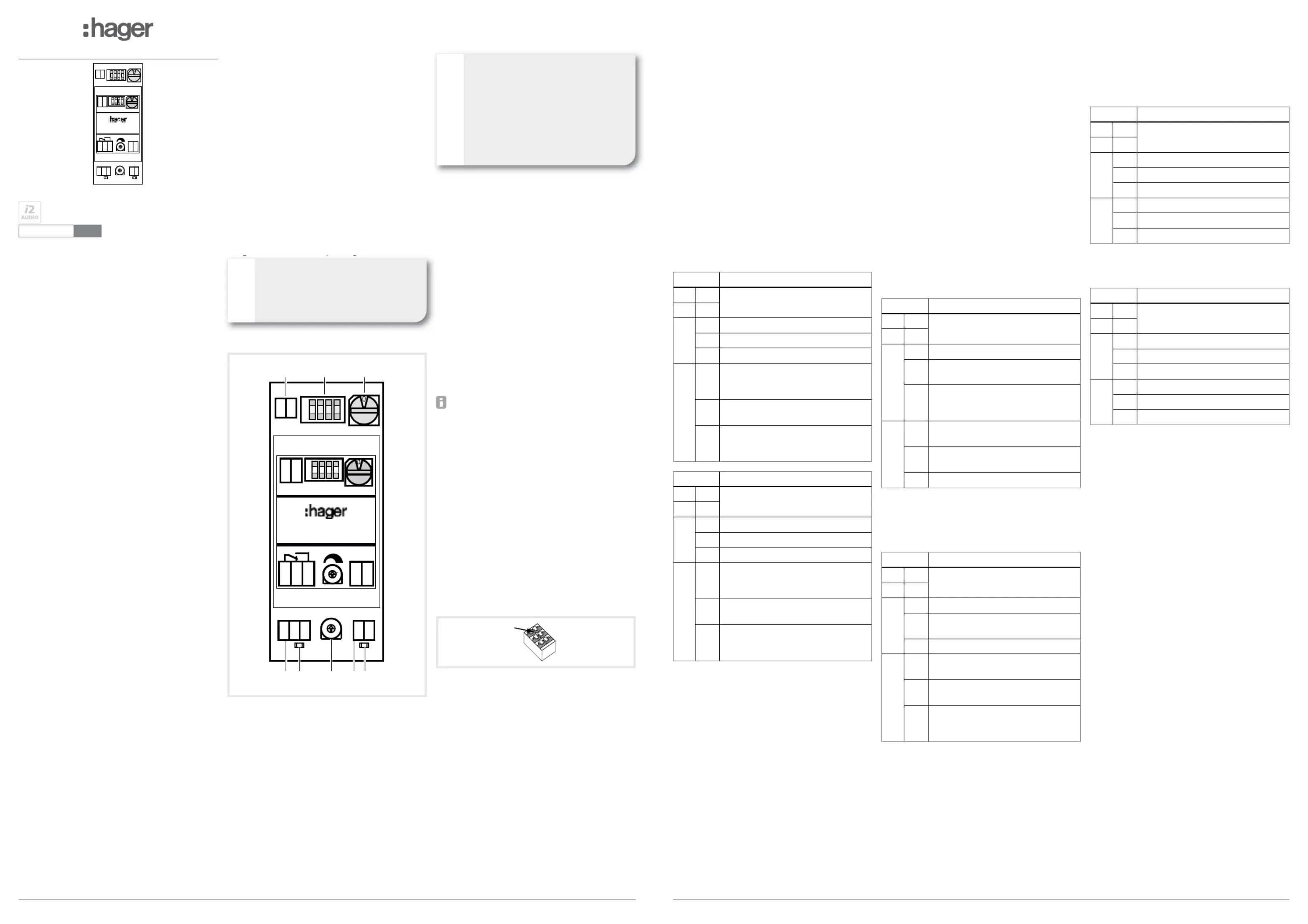
Figure 1: Design and layout of the device
(1) Terminal a/b BUS connection
(2) Operating mode switch: Setting of the switch-
ing functions
(3) Rotary switch S1: Setting of the relay address
(4) Relay terminal: Connection of potential-free
relay contacts (max. 24V/1A)
C = changeover contact, (NC) = NC contact,
NO = NO contact
(5) Relay LED: LED on = relay energized,
LED off = relay de-energized
(6) Rotary control: Setting of the relay switching
duration 0 – 30 seconds
(7) Control input: Connecting terminal for “Con-
trol-In“ control input (12 V AC / 12 V DC)
(8) Control input LED: Indicates the state of the
control input
Information for electricians
Installation and electrical connection
DANGER!
Touching live parts in the installation
environment can result in an electric
shock!
An electric shock can be lethal!
Before working on the device or load,
disconnect all associated circuit
breakers. Cover all live parts in the
area!
ç
When working on systems with a 230 V AC power
connection, comply with the safety requirements of
DIN VDE 0100.
When installing door communication systems,
comply with the general safety regulations for tele-
communications systems according to VDE 0800:
-Separate routing of power and door communi-
cation cables according to VDE 0800.
-Partitions between power and door communica-
tion cables in shared trunkings.
-Use of standard telecommunications' cables,
e. g. J-Y (St) Y with 0.8 mm diameter.
Bus cables
-J-Y(ST)Y or A-2Y(L)2Y
Use wrapped wire pair.
Recommendation: white/yellow
-CAT
Use wrapped wire pair.
Recommendation: orange/white
Avoid interference!
The 13-MHz video carrier frequency used for
two-wire video door communication systems
can cause reciprocal interference with other
devices, such as radios, routers and WLAN
devices.
Only use shielded cables corresponding to
the qualities recommended in this manual.
It is essential to comply with the applicable
regulations during planning and installation.
Route cables, wire the devices, and in
particular implement shielding and earthing
measures as described below.
Connection
Connect conductor: Insert stripped conductor
(solid conductor Ø 0.4 –0.8 mm).
Loosen conductor: Press orange push-button.
Remove conductor.
Figure 2: Connecting terminals
If interference occurs in telecommunications
systems, radio services or other systems during
the operation of existing video door communication
systems, measures for shielding and earthing the
cables and for fi ltering must be implemented.
For this purpose, connect all of the drain wires
of the cables in a star shape using a terminal.
Connect all drain wires to the PE rail in the
distribution box.
Confi guration
"Control-In" control input
The switching relay has a "Control-In" control
input. This can be activated by 12 Volt DC or AC.
Depending on the set mode/parameter, the control
input can be used for various control tasks.
Operating mode switch
The switching relay is confi gured via the operating
mode switches. Here, the switches can have three
states (top = , centre = , bottom = ).+0–
Door release relay and light relay modes
The switching relay switches to this mode when
the door release/light button on the intercom is
pressed.
The activation can be limited to specifi c door,
group or intercom device addresses.
The switching duration can be set from 0 – 30 sec-
onds. An additional operation is via the "Control-In"
possible.
SwitchMode
1+Door release relay
2+
3
+during a door call
0during a door call or in standby
–in standby
4
+only by intercoms with an identical
group/address setting
(rotary switch S1)
0no selection. Activation by all inter-
coms
–only during door calls with an identi-
cal group/address setting
(rotary switch S1)
SwitchMode
10Light relay
2+
3
+during a door call
0during a door call or in standby
–in standby
4
+only by intercoms with an identical
group/address setting
(rotary switch S1)
0no selection. Activation by all inter-
coms
–only during door calls with an identi-
cal group/address setting
(rotary switch S1)
Function relay mode
The "function relay" mode allows switching func-
tions for the comfort intercom special buttons. A
status display of the relay or control input can be
displayed on the comfort intercoms.
-The function relay address is set using the rota-
ry switch S1. A maximum of 16 mutually inde-
pendent switching relays can be operated on a
BUS.
-In , the time that remains ener-Timer mode
gised after releasing the operation button is set
via the rotary control.
-Im Toggle mode, the relay changes its state
each time the operation button is pressed.
-switching relay can also Master function: The
be operated from another switching relay. Here,
a function relay in master mode assumes the
function of a comfort intercom special button.
The "Control-In" control input serves here as a
button input and the relay serves as a status
display.
- You can set whether the Status message:
state of the relay or Control-In input is reported
back to the operating device for visualisation.
SwitchMode
1–Function relay
2+
3
+Relay in toggle mode
0Relay in timer mode time setting via
potentiometer 0-30 seconds
–Master function for controlling an
identically addressed function relay
(rotary switch S1)
4
+Transmitting the state of the relay as
status message
0Transmitting the state of the Con-
trol-in as status message
–transmitting no status message
Door call signalling mode
Door calls can be signalled via the relay by means
of door call signalling. The "Control-In" control
input has no function here.
SwitchMode
1–Door call signalling
20
3
+Audio door calls are signalled
0Audio and video door calls are
signalled
–Video door calls are signalled
4
+only door calls with an identical
group address setting are signalled
0no selection. Signalling via all door
calls
–only door calls from door stations
with an identical door address set-
ting are signalled
Door release/Light direct control modes
A door release/light relay can be controlled with the
door release/light direct control. The function can
be triggered by means of "Control-In" control input;
the relay contacts are disabled during this time.
The address of the relay to be controlled is set
using the rotary switch S1.
SwitchMode
1+Door release direct control*
20
3
+-
0-
–-
4
+Sender address = 1/0
0Sender address = 0/0
–Sender address = F/F
*For direct control of a door loudspeaker-
door release contact or second switching relay
RED112X in door release relay mode
SwitchMode
10Light direct control**
20
3
+-
0-
–-
4
+Sender address = 1/0
0Sender address = 0/0
–Sender address = F/F
**For direct control of an automatic light or second
switching relay in light relay mode
Technical data
Operating voltage via bus 24 V=
Switching contact change-over contact
potential-free max. 24 V/1 A
Control-In input for 12 V ~ / = Input
Degree of protection IP 20
Relative humidity 0 ... 65% (no condensation)
Operating temperature -5 … +45°C
Storage/transport temperature -20 … +60°C
Connecting terminals plug-in terminals
Maximum conductor diameter 0.8 mm
Cable length Control-In input max. 2 m
Dimensions W x H x D
35 x 97 x 58 mm
Space units in the distributor: 2 units
§
Produktspecifikationer
| Varumärke: | Hager |
| Kategori: | Inte kategoriserad |
| Modell: | RED112X |
| Färg på produkten: | Black, Burgundy |
| Vikt: | 5100 g |
| Bredd: | 255 mm |
| Djup: | 370 mm |
| Höjd: | 304 mm |
| Plugg typ: | Type C |
| Sladdlängd: | 5 m |
| Ljudnivå: | 77 dB |
| Årlig-energiförbrukning: | - kWu |
| Förpackningens vikt: | 6100 g |
| Förpackningens bredd: | 284 mm |
| Djuppackning: | 451 mm |
| Förpackningshöjd: | 338 mm |
| Snäll: | Cilinderstofzuiger |
| Kraftkälla: | AC |
| Luftfiltrering av dammsugare: | Hygiënefilter |
| Vakuum: | 21 kPa |
| Räckvidd: | 7.55 m |
| Smutsavskiljningsmetod: | Cyclonisch |
| Typ av rengöring: | Droog |
| Dammkapacitet: | 1.2 l |
| Maximal ineffekt: | 750 W |
| På / Av knapp: | Ja |
| Sladdförvaring: | Ja |
| Ursprungsland: | China |
| Typ av dammsugare: | Zakloos |
| Antalet hjul: | 3 wiel(en) |
| Typ av rör: | Telescopisch |
| Rör/slangmaterial: | Metaal |
| Antal parkerings-/förrådsplatser: | 1 |
| Bärhandtag: | Ja |
| Automatisk sladdupprullare: | Ja |
| Indikator för full dammbehållare: | Ja |
| Antal fartyg: | 1 |
| Korrekt användning: | Thuis |
| Rengör ytor: | Bare floor, Carpet, Hard floor |
| Dammsugarborste ingår: | Parketborstel |
| Antal 360° roterande hjul: | 3 wiel(en) |
| Spaltverktyg: | Ja |
| Luftflöde: | 24 l/s |
| Antal munstycken: | 1 |
| Antal luftfiltersteg: | 3 |
| 2-stegs borste: | Ja |
Behöver du hjälp?
Om du behöver hjälp med Hager RED112X ställ en fråga nedan och andra användare kommer att svara dig
Inte kategoriserad Hager Manualer

2 April 2025
2 April 2025
2 April 2025
2 April 2025
2 April 2025
2 April 2025
2 April 2025
2 April 2025
2 April 2025
1 April 2025
Inte kategoriserad Manualer
Nyaste Inte kategoriserad Manualer
9 April 2025
9 April 2025
9 April 2025
9 April 2025
9 April 2025
9 April 2025
9 April 2025
9 April 2025
9 April 2025
9 April 2025