Hager REU410X Bruksanvisning

Läs gratis den bruksanvisning för Hager REU410X (5 sidor) i kategorin Inte kategoriserad. Guiden har ansetts hjälpsam av 6 personer och har ett genomsnittsbetyg på 4.7 stjärnor baserat på 3.5 recensioner. Har du en fråga om Hager REU410X eller vill du ställa frågor till andra användare av produkten? Ställ en fråga

Sida 1/5
1
z
RE..410..
AUDIO module built-in 2 wire
RE..310..
AUDIO insert replacement built-in
2 wire
6LE002642A Ind. A
Safety instructions
and assembled by a qualied electrician in
accordance with the relevant installation
standards, guidelines, regulations, directives,
safety and accident prevention regulations of
the country.
When installing and laying cables, always
comply with the applicable regulations and
standards for SELV electrical circuits.
These instructions are an integral component
of the product and must be retained by the
end user.
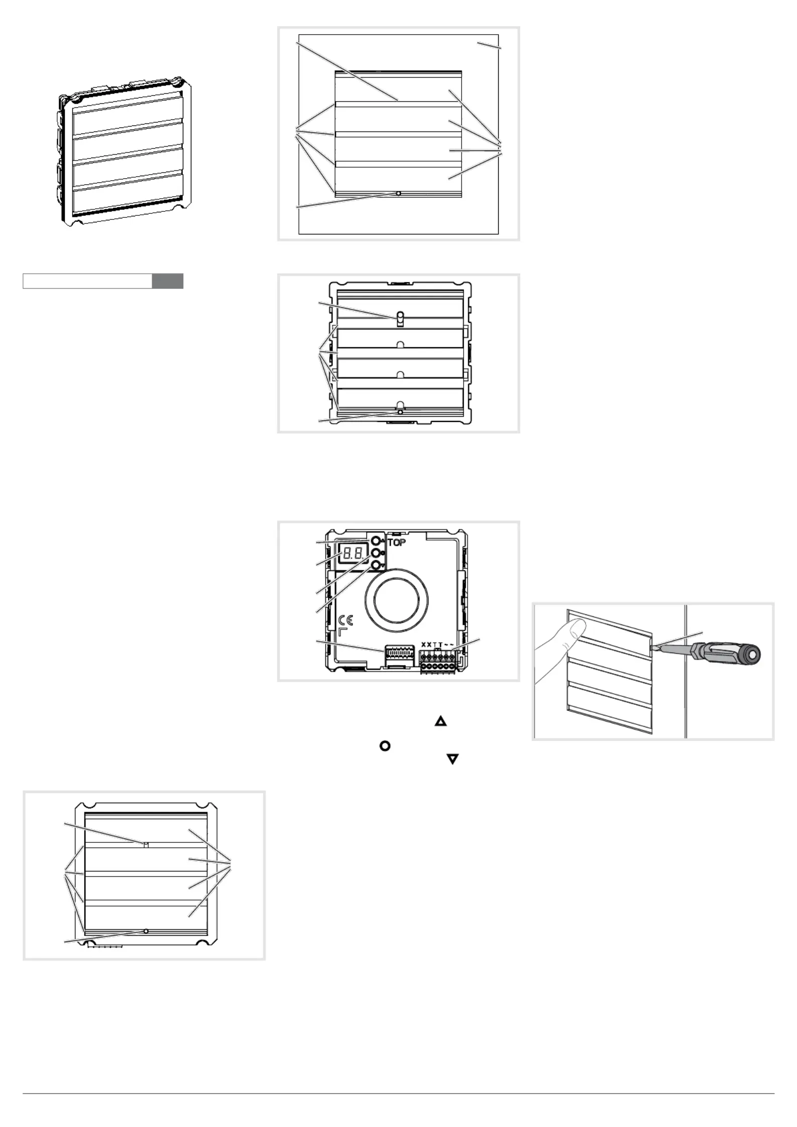
Design and layout of the device
(1)
(3)
(4)
(2)
Figure 1: Design and layout audio module device
front
(1)
(3)
(4)
(2)
(5)
Figure 2: Design and layout audio module with
module carrier device front
(1)
(3)
(2)
Figure 3: Design and layout audio insert device front
(1) Microphone
(2) Speaker
(3) Twilight sensor
(4) Cover plates stainless steel
(5) Module carrier (according to reference)
(6)
(7)
(8)
(9)
(10)
(11)
Figure 4: Design and layout audio modules and
audio-insert back-side
(6) Adjustment button Upwards
(7) 7-segment display
(8) Selection button
(9) Adjustment button downwards
(10) Module bus connector
(11) Connection terminal block
Function
The device works in the 2-wire bus system and
enables communication via sound.
Correct use
- for surface-mounted, ush-mounted or built-in
installation
- Not compatible with intercom systems of other
manufacturers
- suitable for use exterior applications
Product characteristics
- One-man commissioning
- expandable for modules, e.g. call push-button
- Call push-button acknowledge tone (can be
switched off)
- call button, light release or door release can be
adjusted even without any function
- Switch-on brightness level of the call button
backlighting adjustable
- Loudspeaker and microphone protected against
sabotage
- Volume and microphone sensitivity settable
- Door release contact on 1 ... 10 s adjustable
- Door release without previous call adjustable in
single door systems
Operation of call push-buttons
Call push-button modules are connected to the device.
Establish call (ringing)
zPress the call push-button assigned to the
desired subscriber.
If congured, the call push-button activation is
conrmed by an acknowledge tone. Addressed
indoor stations are called.
Switch-on lights
A call push-button is congured and labelled for
lighting control.
zPress the call push-button for lighting.
If congured, the call push-button activation is
conrmed by an acknowledge tone. The light
contact of a line power supply is closed for the
set time.
Label call push-button
zKeep call push-button pressed on one side.
On the opposite side, the lever opening (12) is
accessible for a screwdriver.
zPosition the screwdriver in the lever opening
(12) and release the interlock (Figure 5).
zRemove cover with name plate insert.
(12)
Figure 5: Name plate change
(12) Lever opening
zLabel name plate insert if required.
zInsert name plate insert, prepared foil or
prepared labelling strip into the cover.
zPress on cover.
Do not use any paper for the name plate insert,
since moisture and UV light will damage the
paper and labelling.
UV-resistant foil with laser printing is suitable
for labelling as well as labelling devices for
labelling strip:
- small buttons - 12 mm
- medium buttons - 30 mm
Detailed labelling references are to be found on
our homepage.
P
P
6LE002642A Ind. A
2
Door stations with status indication
Dis-
play
Cause Function/Lighting duration
A subscriber
is called.
After 90 s without call ac-
ceptance or an operation on
the door station, goes out.
A subscriber
accepts the
door call.
goes out,
lights up as
long as the intercom connec-
tion is pressed down, max.
3 min.
The door is
unlocked.
Call not accepted:
Symbol goes out and
lights up for the unlocking
time set on the door station.
Call accepted:
In addition to the
,
the
lights up for the unlocking
time set on the door station.
goes out approx. 5 sec
after the symbol.
Table 1: Status indications of door station
Information for electricians
Installation and electrical connection
DANGER!
Touching live parts in the installation
environment can result in an electric
shock!
An electric shock can be lethal!
Before working on the device or load,
disconnect all associated circuit
breakers. Cover all live parts in the
area!
ç
When installing door communication systems,
comply with the general safety regulations for
telecommunications systems according to VDE
0800:
- Separate routing of power and door
communication cables with a minimum spacing
of 10 cm
- Partitions between power and door
communication cables in shared trunkings
- Use of standard telecommunications cables,
e. g. J-Y (St) Y with 0.8 mm diameter
Bus cables
- J-Y(ST)Y or A-2Y(L)2Y
Use wrapped wire pair.
Recommendation: white/yellow
- CAT
Use wrapped wire pair.
Recommendation: orange/white
- YR
Use adjacent wires.
Installing the device
An installation height of approx. 1.5 m (middle
of the loudspeaker) is recommended for
persons of average size.
Installation of the device depends upon the
respective product it is going to be installed in
(see already available installation instruction,
e.g. door station, frame, etc.).
P
P
Connect device
The connection cables and indoor stations are
connected to the line power supply while taking
the maximum cable lengths and attenuations into
account (see operating instructions of the line power
supply).
zBring pre-assembled station (door station,
frame, etc.) in installation position - if necessary
with safety rope and tools.
zShorten connection cable of the device as
required and strip the required wires.
zPull off connection terminal block (11) from the
device.
zConnect the wire pair of the 2-wire bus cable
block (Figure 6).
zConnect door release cable to the terminals TT
of the connection terminal block (gure 6 and 7)
if required.
or:
zFor manipulation-protected installation, connect
the door release to the contact
of the line
power supply (Figure 8).
The door release lead must not be inserted
through the door station in order to protect
against manipulation.
zFor call push-button backlighting connect 12
V~ lead from the power transformer to the
terminals of the connection terminal block ~~
(Figure 6... 8).
(11)
Figure 6: Wired connection terminal block
zAttach connector of the module connection
cable to the next call push-button module on
the device.
zAttach connection terminal block to the device.
zEngage and screw in the module e.g. in the
rear latching receptacle of a door station (see
corresponding mounting instructions).
zClose station
Circuit symbols and elements of the circuit
diagrams
Line power supply RMD
Power transformer
Door release
Door station audio
Wrapped wire pair for 2-wire devices (recom-
mendation: white/yellow wire pair)
Unwrapped wire pair, for e.g. for door release
P
Figure 7: Door release station on the device
Figure 8: connection of device with manipulation
protected door release
3
Calling up and navigating system settings
On the back of the device, there are 3 buttons and
a 2-digit 7-segment display (Figure 4, 6-9) for the
system settings . 9).
zPress
/ button.
Device turns to setting mode. The rst menu
entry is displayed.
The reading directions of the 7-segment display
varies by 180° depending on which button
/
you start with.
zSelect the desired menu entry with
/
(gure 9).
zConrm the selection with
.
The 7 segments display goes dark if there is no
actuation for 5 seconds. Settings are applied.
The device returns to normal operation.
Setting the values
The menu entry to be set is conrmed and ashes
alternately with the value to be set.
zPress
/ button.
Short button-press: change the value by one
step.
Long button-press: run through values. Scrolling
stops when the button is released.
zConrm set value with
The device applies the setting and returns to
the previous menu entry.
Address call push-button automatically
The call push-button and connector on the back
are addressed by the automatic call push-button
addressing as follows. The addressing, e.g. with
two-rowed door stations, takes place starting from
the top downwards, and with a two-rowed door
station, counterclockwise automatically upwards to
the right (gure 10).
The menu entry
is conrmed. ashes
alternately with the entry for cancel.
zWith
/ select the entry for automatic
addressing.
zConrm with
.
During the addressing, the display ickers.
Afterwards the display returns to the previous
menu entry
.
0/0
0/1
0/0
0/1
0/2
0/2
0/3
0/4
0/3
0/4
0/5
0/6
0/7
0/F
0/E
0/D
0/C
0/B
0/A
0/9
0/8
Figure 10: Module address and automatic call
push-button addressing
Set individual call push-button address/function
The menu entry Set individual call push-button
address/function is conrmed and ashes.
zConrm the call push-button to be set.
The menu entry
ashes alternately with the
current address/function.
zWith
/ select the required address ...
or function for light push-button, for
door release push-button or
for no function.
P
P
Individual call push-
button address/function
Automatic call push-
button addressing
Door speaker
volume
Microphone sensiti-
vity
Operating sig-
nal sound volume
Door release
unlocking time
Door release
function
set
door address
Camera present
Call push-button
Backlighting
settings
(switch-on
brightness level)
Display error
codes (max. 5 can
be saved)
Reset error codes
factory setting
Conrm the call
push-button to be set
... = Call push-button address
= Light push-button
= Door release push-button
= no function
Address/Function
saved,
is displayed
= Cancel
= Start addressing
Addressing executed/cancelled,
is displayed
...
Default setting
Volume set,
is displayed
...
Default setting
Sensitivity set.
is displayed
...
= Acoustic signal off
Default setting
Volume set,
is displayed
... Seconds
Default setting seconds
Unlocking time set,
is displayed
= only with door call
= also without door call
1
)
Default setting
Door release function is set,
is displayed
x
... x
x = received line
address
Default setting
Door address set,
is displayed
= No camera
= with camera
Default setting: Audio
Video
Camera option set,
is displayed
...
= Off
= lowest value
= highest value
= always on
Default setting
Backlighting set,
is displayed
... Error codes
= module communication
= sticking call button
= module address
= no error present
= Cancel
= Reset
Error codes were deleted,
is deleted
Error codes were displayed,
is displayed
= Cancel
= Reset
Reset to the factory setting, in
-
dication goes out
1)
Door release functions without door call only possible single door systems
Figure 9: Overview of system settings

Produktspecifikationer

Varumärke: Hager
Kategori: Inte kategoriserad
Modell: REU410X
Typ av operation: Buttons, Rotary
Vikt: 37000 g
Bredd: 595 mm
Djup: 595 mm
Höjd: 548 mm
Grill: Ja
Energie-efficiëntieklasse: A
Energie consumptie: 0.66 kWu
Belysning inuti: Ja
Integrerad klocka: Ja
Typ av klocka: Elektronisch
Total inomhuskapacitet (ugnar): 65 l
Antal ugnar: 1
Lätt att städa: Ja
Mått för installationsfack (BxDxH): 560 x 550 x 600 mm
Nuvarande: 16 A
Typ av ugn: Elektrische oven
Total ugnseffekt: 11600 W
Ugn med nettokapacitet: 65 l
Över- och undervärme: Ja
Ugnens termostatområde: 50 - 300 °C
Ugnskraft: 11600 W
AC-ingångsspänning: 220 - 240 V
Strömförbrukning (typiskt): 11600 W

Behöver du hjälp?

Om du behöver hjälp med Hager REU410X ställ en fråga nedan och andra användare kommer att svara dig