Hager REU610X Bruksanvisning
Hager
Inte kategoriserad
REU610X
Läs gratis den bruksanvisning för Hager REU610X (5 sidor) i kategorin Inte kategoriserad. Guiden har ansetts hjälpsam av 14 personer och har ett genomsnittsbetyg på 4.5 stjärnor baserat på 7.5 recensioner. Har du en fråga om Hager REU610X eller vill du ställa frågor till andra användare av produkten? Ställ en fråga
Sida 1/5

1
z
RE..610..
Video module 2-wire
RE..510..
Video insert replacement 2-wire
6LE002632A Ind. A
Safety instructions
Electrical equipment may only be installed and
assembled by a qualied electrician in
accordance with the relevant installation
standards, guidelines, regulations, directives,
safety and accident prevention regulations of
the country.
When installing and laying cables, always
comply with the applicable regulations and
standards for SELV electrical circuits.
These instructions are an integral component
of the product and must be retained by the end
user.
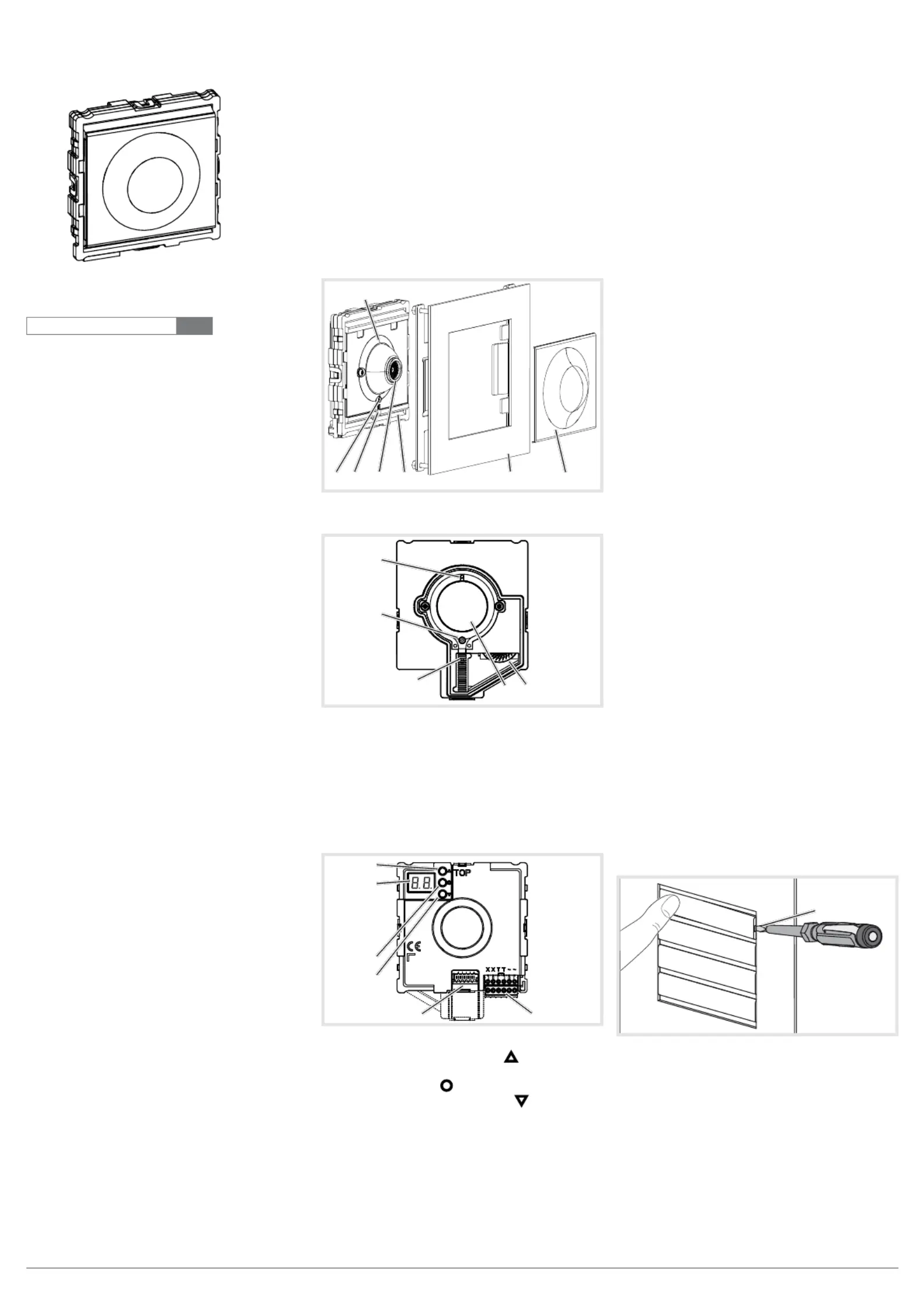
Design and layout of the device
(1)
(4)
(5)(3) (6) (7)(2)
Figure 1: Front video module
(1)
(3)
(4)
(2)
(5)
Figure 2: Front video insert
(1) Microphone
(2) Locating screw for camera
(Allen key supplied)
(3) Twilight sensor for call button
(4) Camera
(5) Loudspeaker openings
(6) Module carrier (according to reference)
(7) Centre plate (only with video modules)
(8)
(9)
(10)
(11)
(12) (13)
Figure 3: Back
(8) Adjustment button Upwards
(9) 7-segment display
(10) Selection button
(11) Adjustment button downwards
(12) Connection for module connecting cable
(13) Connection terminal block
Function
The device works in the 2-wire bus system and
enables communication via sound and image.
Correct use
- for surface-mounted, ush-mounted or built-in
installation
- Not compatible with intercom systems of other
manufacturers
- suitable for use exterior applications
Product characteristics
- One-man commissioning
- expandable for modules, e.g. call push-button
- Call push-button acknowledge tone (can be
switched off)
- Call button, light release or door release can be
adjusted even without any function
- Switch-on brightness level of the call button
backlighting adjustable
- Colour camera
- invisible, glare-free IR LED night lighting
- temperature controlled camera heating for clear
view
- scratch-proof camera cover
- Loudspeaker and microphone protected against
sabotage
- Volume and microphone sensitivity settable
- Door release contact on 1 ... 10 s adjustable
- Door release without previous call adjustable in
single door systems
Operation of call push-buttons
Call push-buttons are connected to the device.
Establish call (ringing)
zPress the call push-button assigned to the
desired subscriber.
If congured, the call push-button activation is
conrmed by an acknowledge tone. Addressed
indoor stations are called.
Switch-on lights
A call push-button is congured and labelled for
lighting control.
zPress the call push-button for lighting.
If congured, the call push-button activation is
conrmed by an acknowledge tone. The light
contact of a line power supply is closed for the
set time.
Label call push-button
zKeep call push-button pressed on one side.
On the opposite side, the lever opening (14) is
accessible for a screwdriver.
zPosition the screwdriver in the lever opening
(14) and release the interlock (Figure 4).
zRemove cover with name plate insert.
(14)
Figure 4: Removing name plate cover
(14) Lever opening
zLabel name plate insert if required.
zInsert name plate insert, prepared foil or prepa-
red labelling strip into the cover.
zPress on cover.
Do not use any paper for the name plate insert,
since moisture and UV light will damage the
paper and labelling.
P
6LE002632A Ind. A

2
UV-resistant foil with laser printing is suitable
for labelling as well as labelling devices for
labelling strip:
- small buttons - 12 mm
- medium buttons - 30 mm
Detailed labelling references are to be foun on
our homepage.
Door stations with status indication
Dis-
play
Cause Function/Lighting
duration
A subscriber is
called.
After 90 s without call
acceptance or an operati-
on on the door station,
goes out.
A subscriber
accepts the
door call.
goes out,
lights up as
long as the intercom con-
nection is pressed down,
max. 3 min.
The door is
unlocked.
Call not accepted:
Symbol goes out and
lights up for the unlok-
king time set on the door
station.
Call accepted:
In addition to the
,
the
lights up for the unlok-
king time set on the door
station.
goes out approx.
5 sec after the
symbol.
Table 1: Status indications of door station
Information for electricians
Installation and electrical connection
DANGER!
Touching live parts in the installation
environment can result in an electric
shock!
An electric shock can be lethal!
Before working on the device or load,
disconnect all associated circuit brea-
kers. Cover all live parts in the area!
ç
When installing door communication systems,
comply with the general safety regulations for tele-
communications systems according to VDE 0800:
- Separate routing of power and door communi-
cation cables with a minimum spacing of 10 cm
- Partitions between power and door communica-
tion cables in shared cable ducts
- Use of standard telecommunications’ cables, e.
g. J-Y (St) Y with 0.8 mm diameter
Bus cables
- J-Y(ST)Y or A-2Y(L)2Y
Use wrapped wire pair.
Recommendation white/yellow
- CAT
Use wrapped wire pair
Recommendation orange/white
- YR
Use adjacent wires
Installing the appliance
An installation height of approx. 1.5 m (middle
of the camera lens) is recommended for per-
sons of average size.
Installation of the device depends upon the
respective product it is going to be installed in
(see installation instruction, e.g. door station,
frame, etc.).
P
P
P
Connect device
The connection cables and indoor stations are
connected to the line power supply while taking
the maximum cable lengths and attenuations into
account (see operating instructions of the line power
supply).
zBring pre-assembled station (door station,
frame, etc.) in installation position - if necessary
with safety rope and tools.
zShorten connection cable of the station as
required and strip the required wires.
zPull off connection terminal block (13) from the
device.
zConnect the wire pair of the 2-wire bus cable
to the terminals of the connection terminal XX
block (Figure 5).
zConnect door release to the terminals of TT
the connection terminal block (gure 5 and 6) if
required.
or:
zFor manipulation-protected installation, connect
the door release to the contact
of the line
power supply (Figure 7).
The door release lead must not be inserted
through the door station in order to protect
against manipulation.
zFor call push-button backlighting and camera
heating connect 12 V~ lead from the power
transformer to the terminals of the connecti-~~
on terminal block (Figure 5 ... 7).
(13)
Figure 5: Wired connection terminal block
zAttach connector of the module connection
cable to the next call push-button module on
the device.
zAttach connection terminal block to the device.
zEngage and screw in the module e.g. in the
rear latching receptacle of a door station (see
corresponding mounting instructions).
zClose station.
Circuit symbols and elements of the circuit
diagrams
Line power supply RMD
Power transformer
Door release
Video door station
Wrapped wire pair for 2-wire devices (recom-
mendation: white/yellow wire pair)
Unwrapped wire pair, for e.g. for door release
P
Figure 6: Door release connection on the door
station
Figure 7: Connection of door station video with
manipulation-protected door release
Calling up and changing of system settings
On the back of the device, there are 3 buttons and
a 2-digit 7-segment display (Figure 3, 8 ... 11) for
the system settings.
zPress
/ button.
Device turns to setting mode. The rst menu
entry is displayed.
The reading directions of the 7-segment display
varies by 180° depending on which button
/
you start with.
zSelect the desired menu entry with
/
(gure 9).
zConrm the selection with
.
The 7 segments display goes dark if there is no
actuation for 5 seconds. Settings are applied.
The device returns to normal operation.
Setting the values
The menu entry to be set is conrmed and ashes
alternately with the value to be set.
zPress
/ button.
Short button-press: change the value by one
step.
Long button-press: run through values. Scroll-
ing stops when the button is released.
zConrm set value with
.
The device applies the setting and returns to
the previous menu entry.
Address call push-button automatically
The call push-button and connector on the back
are addressed by the automatic call push-button
addressing as follows. The addressing, e.g. with
two-rowed door stations, takes place starting from
the top downwards, and with a two-rowed door
station, counterclockwise automatically upwards to
the right (gure 8).
The menu entry
is selected. - ashes alter
nately with the entry
for cancel.
zWith
/ select the entry for automatic
addressing.
zConrm with
.
During the addressing, the display ickers.
Afterwards the display returns to the previous
menu entry
.
P
P

3
0/0
0/1
0/0
0/1
0/2
0/2
0/3
0/4
0/3
0/4
0/5
0/6
0/7
0/F
0/E
0/D
0/C
0/B
0/A
0/9
0/8
Figure 8: Module address and automatic call
push-button addressing
Set individual call push-button address/function
The menu entry Set individual call push-button
address/function is selected and ashes.
zConrm the call push-button to be set.
The menu entry
ashes alternately with the
current address/function.
zWith
/ select the required address ...
or function for light push-button, for
door release push-button or for no function.
zConrm set address/function with
.
The device applies the setting and returns to
the previous menu entry
.
Display saved error codes
Device errors that occur during operation are
stored in the the error memory of the device for
diagnosis.
zSelect menu entry
with button / and
conrm with .
If no error code exists
is displayed for 2
seconds and afterwards .
If error codes are saved
ashes followed
by the module address and the error code.
zPress button
/ , to call up further error
codes if necessary.
zPress button
to return to menu entry .
Error
code
Error cause Counter actions
Communication error
between device and
call push-button mod-
ule. Once the error
has occurred 3 times,
the system is reset
automatically and the
error code is gener-
ated.
If the error per-
sists, the call
push-button
module must be
replaced.
sticking call button Check call
push-button
module If there
is a defect, re-
place and ad-
dress.
Writing of the call
push-button address
in the call push-button
module fails.
If the error per-
sists, the call
push-button
module must be
replaced and
re-addressed.
Table 2: Error codes and counter actions
The memory should only be deleted once 5
error codes have been stored, so that new error
codes can be saved.
Identical error codes are only saved once.
Align camera
The camera can be aligned in order to adapt the
camera picture to the local circumstances (Figure
10 and 14).
The door station is installed.
zWith door stations with video module: unlock
centre plate at the dismantling opening (15)
carefully with a screwdriver and remove then.
(15)
Figure 10: Dismantling video module centre plate
(15) Dismantling opening
zLoosen the locating screw (2) for the camera
with the 1.5 mm Allen key supplied
(Figure 11 or 12).
zCall an indoor station video from the door sta-
tion by call push-button.
Figure 11: Camera alignment video module
P
P
Individual call push-
button address/function
Automatic call push-
button addressing
Door speaker
volume
Microphone
sensitivity
Operating sig-
nal sound volume
Door release
unlocking time
Door release
function
set
door address
Camera present
Call push-button
Backlighting settings
(switch-on brightness
level)
Display error codes
(max. 5 can be saved)
Reset error codes
factory setting
Conrm the call push-
button to be set
... =
Call push-button address
= Light push-button
=
Door release push-but
ton
= no function
Address/Function
saved,
is displayed
= Cancel
= Start addressing
Addressing executed/can
-
celled, is displayed
...
Default setting
Volume set,
is displayed
...
Default setting
Sensitivity set.
is displayed
...
= Acoustic signal off
Default setting
Volume set,
is displayed
... Seconds
Default setting seconds
Unlocking time set,
is displayed
= only with door call
= also without door call
1
)
Default setting
Door release function is set,
is displayed
x
... x
x = received line
address
Default setting
Door address set,
is displayed
= No camera
= with camera
Default setting: Audio
Video
Camera option set,
is displayed
...
= Off
= lowest value
= highest value
= always on
Default setting
Backlighting set,
is displayed
... Error codes
=
module communication
= sticking call button
= module address
= no error present
= Cancel
= Reset
Error codes were deleted,
is deleted
Error codes were displayed,
is displayed
= Cancel
= Reset
Reset to the factory setting, in
-
dication goes out
1) Door release functions without door call only possible single door systems
Figure 9: Overview of system settings
Produktspecifikationer
Varumärke: | Hager |
Kategori: | Inte kategoriserad |
Modell: | REU610X |
Färg på produkten: | Zwart |
Inbyggda högtalare: | Ja |
Genomsnittlig effekt: | 300 W |
Typ av enhet: | DVD speler |
Kompositvideoutgång: | 1 |
S-videoutgång: | 1 |
Komponentutgång video (YPbPr/YCbCr): | 1 |
Typ-av-optisk-enhet: | CD, DVD |
Mått (B x D x H): | 942 x 447.5 x 623.3 mm |
Behöver du hjälp?
Om du behöver hjälp med Hager REU610X ställ en fråga nedan och andra användare kommer att svara dig
Inte kategoriserad Hager Manualer
2 April 2025
2 April 2025
2 April 2025
2 April 2025
2 April 2025
2 April 2025
2 April 2025
2 April 2025
2 April 2025
1 April 2025
Inte kategoriserad Manualer
- HDFury
- Nuki
- Gator
- Dorr
- Barkan
- Elinchrom
- ADATA
- Autodesk
- Kingston
- Constructa
- Thames & Kosmos
- Concept
- Pentair
- Gaslock
- Kontakt Chemie
Nyaste Inte kategoriserad Manualer
9 April 2025
9 April 2025
9 April 2025
9 April 2025
9 April 2025
9 April 2025
9 April 2025
9 April 2025
9 April 2025
9 April 2025