Humminbird Helix 12 Chirp SI GPS Bruksanvisning
Humminbird fiske ekolod Helix 12 Chirp SI GPS
Läs gratis den bruksanvisning för Humminbird Helix 12 Chirp SI GPS (13 sidor) i kategorin fiske ekolod. Guiden har ansetts hjälpsam av 45 personer och har ett genomsnittsbetyg på 4.0 stjärnor baserat på 9 recensioner. Har du en fråga om Humminbird Helix 12 Chirp SI GPS eller vill du ställa frågor till andra användare av produkten? Ställ en fråga
Sida 1/13
1
532405-6_B
HELIX® SERIES CONTROL HEAD Installation Guide
Follow the instructions in this installation guide to gimbal mount the control head.
NOTE:Your gimbal bracket may not look exactly like the gimbal bracket shown in the illustrations, but it will mount in exactly the same way.
Installation Preparation
Read the instructions in this transducer guide completely to understand the mounting guidelines before starting the installation.
Visit our Web site at humminbird.com for additional information and resources for transducer installations. Also, visit
youtube.com/humminbirdtv for informational videos.
Supplies: In addition to the hardware supplied with your control head, you will need a powered hand drill and various drill bits, Phillips
head screwdriver, flat head screwdriver, pencil, safety glasses and dust mask, marine-grade silicone sealant, dielectric grease
(optional), extension cables (optional), Ethernet cables (optional), and accessory cables (optional). Also, see Connect Power to
determine the type of connection, fuse size, and additional equipment you will need for the installation.
Accessories and Ethernet: Accessories and Ethernet equipment are available for purchase at humminbird.com. The installation
guides are available with the product, or they can be downloaded from our Web site.
Installation Overview
1
|
Plan the Mounting Location
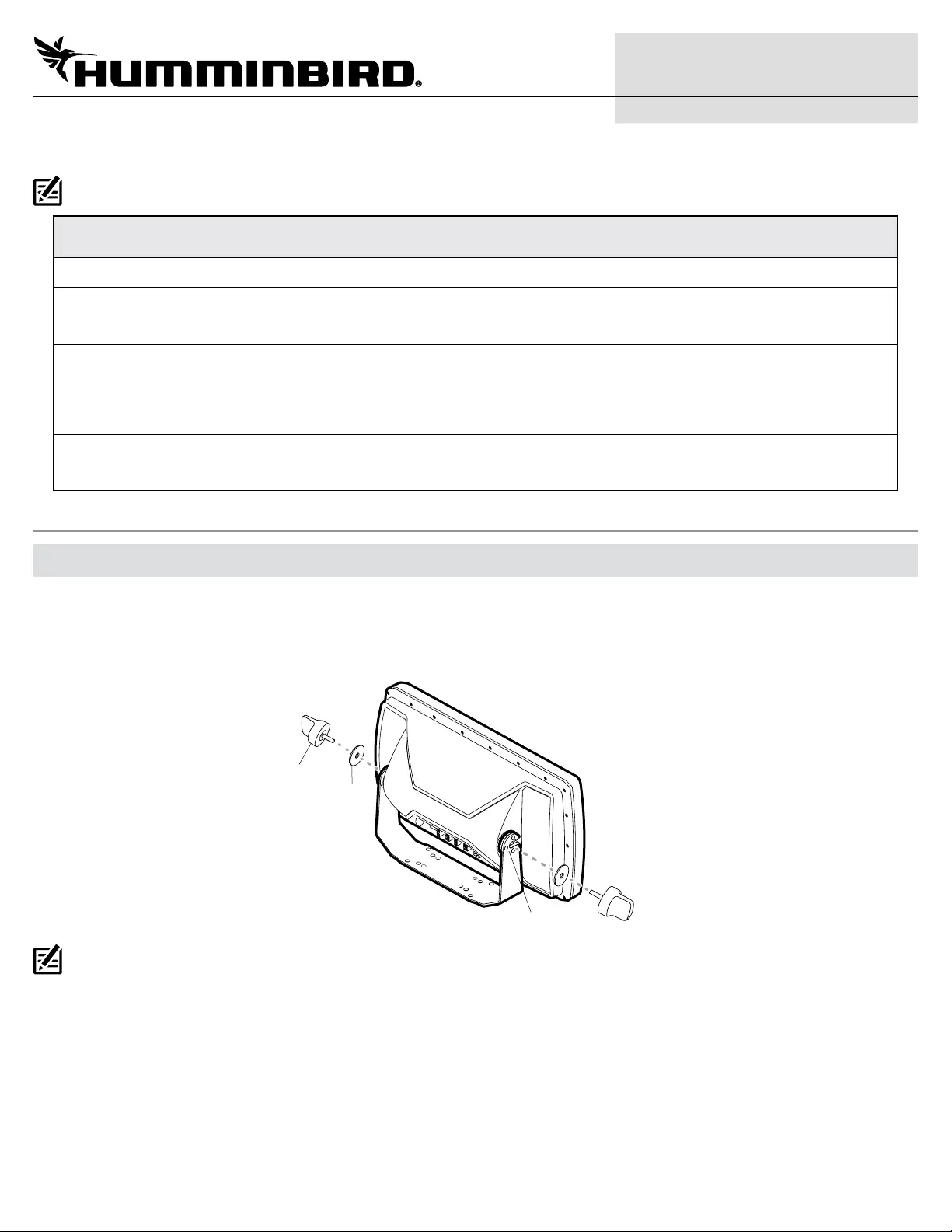
1. Place 1 rubber washer onto each gimbal knob.
2. Install the gimbal knobs (with washers) into each side of the control head. Tighten the knobs just enough so you can slide the control
head into the gimbal bracket arms.
Assembling the Control Head and Bracket
gimbal
knob
bracket arm
rubber
washer
NOTE: If you prefer to mount the control head overhead, flip the bracket to the top of the control head. The opening in the gimbal bracket arms
must face the rear of the control head.
3. Place the assembled control head in various locations to determine the best mounting location with the following requirements:
∆a stable, protected surface to protect the control head from excessive wave shock, vibration, and water
∆sufficient space for the control head tilt range
∆visibility during operation, as well as easy installation and removal
∆access above and below the mounting surface to pass the cables through to the control head
∆space for the 1" (25 mm) cable hole located 2" to 4" (50 to 100 mm) behind the chosen mounting location
4. Test route all cables (transducer, power, Ethernet, accessories) to the control head mounting location. Leave enough cable length for
installing the cable tray and for the control head tilt range.
5. After you have selected the mounting location, loosen the gimbal knobs and remove the control head from the gimbal bracket.
Produktspecifikationer
| Varumärke: | Humminbird |
| Kategori: | fiske ekolod |
| Modell: | Helix 12 Chirp SI GPS |
Behöver du hjälp?
Om du behöver hjälp med Humminbird Helix 12 Chirp SI GPS ställ en fråga nedan och andra användare kommer att svara dig
fiske ekolod Humminbird Manualer

27 Juli 2025
27 Juli 2025
27 Juli 2025
26 Juli 2025
26 Juli 2025
26 Juli 2025
26 Juli 2025
fiske ekolod Manualer
Nyaste fiske ekolod Manualer
6 Mars 2026
20 September 2025
20 September 2025
12 September 2025
10 September 2025
10 September 2025
10 September 2025
10 September 2025
10 September 2025
10 September 2025