Lectrosonics DHu Bruksanvisning

Läs nedan 📖 manual på svenska för Lectrosonics DHu (20 sidor) i kategorin Inte kategoriserad. Denna guide var användbar för 15 personer och betygsatt med 4.8 stjärnor i genomsnitt av 8 användare

Sida 1/20
Rio Rancho, NM, USA
www.lectrosonics.com
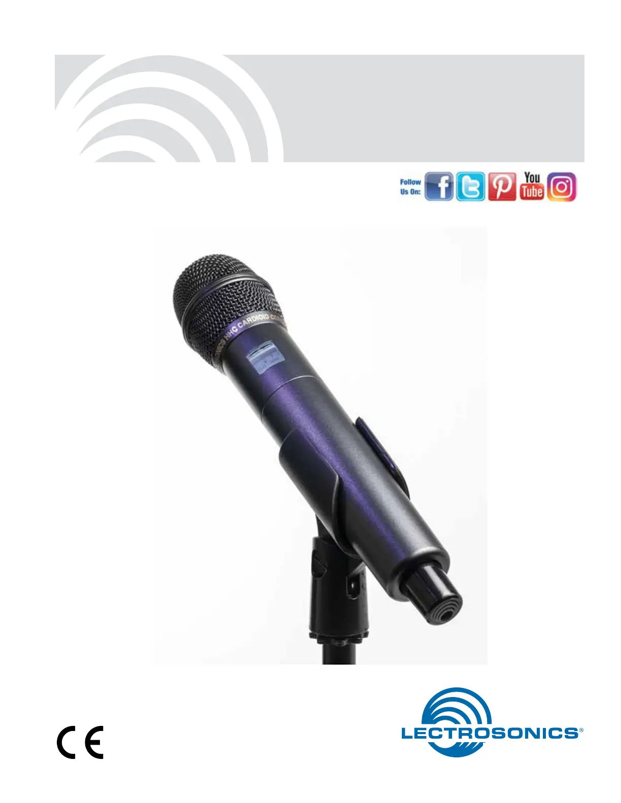
INSTRUCTION MANUAL
DHu
Digital Handheld Transmitter
DHu, DHu/E01
DHu
LECTROSONICS, INC.
2
, DHu/E01
Table of Contents
General Technical Description .......................................... 3
Microphone Capsules: ....................................................... 4
Mechanical Assembly 4 ........................................................
Battery Installation 5 .............................................................
Control Panel 5 ......................................................................
Setup and Adjustments 6 .....................................................
Powering On 6 .....................................................................
Powering Off 6 .....................................................................
Standby Mode 6 ...................................................................
Power Menu 6 ......................................................................
Navigating Menus and Screens 7 ........................................
Menu Map 7 ............................................................................
Input Gain Adjustment 10 .......................................................
Programmable Switch Functions 10 ......................................
Parts and Accessories 12 .......................................................
Mic Capsule Adjustments 13 ..................................................
(EXPERT LEVEL ADJUSTMENT) 13 ....................................
Specifications 14 .....................................................................
Wireless Designer Software 14 .............................................
Firmware Update Instructions 14 ...........................................
Troubleshooting 15 ..................................................................
Service and Repair 17 .............................................................
Returning Units for Repair 17 ................................................
Declaration of Conformity.................................................. 18
Digital Hand Held Transmitter
Rio Rancho, NM 3
General Technical Description
Introduction
The transmitter benefits from a fourth generation
design with specially developed, high efficiency digital
circuitry for extended operating time on two AA batter-
ies. The transmitter can tune across the UHF televi-
sion band from 470.100 to 607.950 MHz (470.100 to
614.375 for export), with a selectable output power
of 25 or 50 mW. The pure digital architecture enables
AES 256-CTR encryption for applications that require
high level security.
Input Gain Range and Limiter
45 dB range of input gain adjustment allows gain
settings to accurately match the user’s voice and the
varying sensitivity of different microphone capsules. A
DSP-controlled analog audio limiter is employed be-
fore the A-D converter. The limiter has a range of more
than 30 dB for excellent overload protection. A dual re-
lease envelope makes the limiter acoustically transpar-
ent while maintaining low distortion. It can be thought
of as two limiters in series, a fast attack and release
limiter followed by a slow attack and release limiter.
The limiter recovers quickly from brief transients, with
no audible side effects, and also recovers slowly from
sustained high levels to keep audio distortion low while
preserving short term dynamics.
Frequency Selection
Operating frequency is normally selected using a
receiver or analyzer to assess signals in the local en-
vironment to avoid interference. Once an interference-
free frequency is identified, the transmitter frequency is
set to match the receiver.
The LCD on the transmitter displays frequency in MHz
and with a two character hex code that is used on
most Lectrosonics receivers.
Antenna
A unique helical antenna allows the transmitter to be
held in any position, since the user’s hands have little
or no effect on the RF output power.
Microphone Capsules
The transmitter is available from Lectrosonics with
the HHC and HHVMC cardioid condenser capsules.
Capsules from several other manufacturers are also
available for use with the DHu, DHu/E01: those with a
1.25” x 28 thread pitch and three contact rings. Con-
denser or dynamic microphone capsules can be used
to suit the user’s preference or the application.
Encryption
When transmitting audio, there are situations where
privacy is essential, such as during professional
sporting events, in court rooms or private meetings.
For instances where your audio transmission needs
to be kept secure, without sacrificing audio quality,
Lectrosonics introduces Encryption Keys. Truly entro-
pic encryption keys are first created by a Lectrosonics
receiver, such as the DSQD Receiver. The key is then
synced with the DHu, DHu/E01 via the IR port. The
audio will be encrypted and can only be listened to if
both DHu, DHu/E01 and receiver have the matching
encryption key. If you are trying to transmit an audio
signal and keys do not match, all that will be heard is
silence or white noise.
IR (infrared) Sync
An IR Sync Port is used for quick setup with receivers
that offer this feature. Settings for frequency, step size
and compatibility mode are transferred from receiver to
transmitter via the IR ports.
Side Button Functions
A programmable switch on the side of the housing can
be configured as a mute/cough switch, a power switch
or be disabled.
USB Port for Key Transfer and Firmware Updates
The encryption key is generated in the receiver, then
transferred to the transmitter via a USB port using a
cable. This requires that the user be in direct contact
with both units, which increases the security level.
Firmware updates are enabled by simply downloading
a file and utility program from the Lectrosonics web
site, connecting the transmitter to a computer via the
USB port and running the program.
DHu
LECTROSONICS, INC.
4
, DHu/E01
A mic capsule is
threaded onto the body
of the transmitter in the
direction shown.
Do not overtighten it. The lower housing opens by rotating
it in the direction shown. After the
threads are disengaged, pull the
housing downward until it engages
the detent that holds it open.
The threaded interface is a 1.25”
diameter opening with 28 threads
per inch and three contact rings
Mechanical Assembly
Microphone Capsules:
Lectrosonics offers two types of capsules. The HHC is
the standard capsule and the HHVMC is the Variable
Mic Capsule which includes adjustments for Bass,
Midrange and Treble.
HHC Lectrosonics
cardioid electret
HHVMC Lectrosonics cardioid
electret with VariMic preamp
Along with these two models from Lectrosonics, a
variety of different capsules with a common thread
and electrical interface are available from the major
microphone manufacturers.
A list of compatible capsules is on the website at www.
lectrosonics.com listed the DHu, DHu/E01 product
page.
Do not touch the contacts between the mic capsule
and transmitter body. When necessary, the contacts
can be cleaned with a cotton swab and alcohol.
*All product names are trademarks of their respective
owners, which are in no way affiliated with Lectrosonics.
Capsule Installation
Capsules are attached with a right-hand thread.
To remove the windscreen from the mic capsule,
line up the blue wrench (included with the capsule
head) with the flat notches on the lower threaded area
of the mic capsule.
Align flats on the wrench with flats on the capsule.
DHu
LECTROSONICS, INC.
6
, DHu/E01
Setup and Adjustments
Powering On
Press and hold the Power Button until a status bar on
the LCD is completed. The status bar will appear on
the LCD, followed by a display of the model, firmware
version, frequency band and compatibility mode.
DHu
V1.01
Hold
for
Rf O n
When you release the button, the unit will be opera-
tional with the RF output turned ON and the Main
Window displayed.
DHu
545.400
-40 -20 0
The Main Window
RF output ON
If you release the button before the countdown is com-
plete, the unit will turn on in the Standby mode with the
RF output turned OFF and the antenna icon will blink.
DHu
545.400
-40 -20 0
The Main Window
RF output OFF
Powering Off
Press and hold the Power Button (or the side button if
it is configured for turning the power on and off) while
the status bar on the LCD is completed. The power will
then be turned off. This can be done from any menu or
screen.
Powering
O . . .
NOTE: If the Power Button
is released before the
countdown is completed, the
unit will remain turned on
and the LCD will return to the
same screen or menu that
was displayed previously.
Standby Mode
A brief push of the keypad Power Button turns the unit
on and places it into a “standby” mode (not transmit-
ting). Press the button and release before the status
bar completes. This allows the transmitter to be set up
without the risk of creating interference for other wire-
less systems that are operating in the vicinity.
A notice will appear briefly confirming that the RF out-
put of the transmitter is turned off, followed by the Main
Window The antenna symbol will blink as a reminder .
that the RF output is turned off.
DHu
545.400
-40 -20 0
Symbol blinks
when RF output
is turned OFF
Rf
Off
Power Menu
Resume
Pwr Off
Rf On?
Backlit
When the transmitter is turned on, a
brief push of the Power Button on
the keypad will reveal a menu
allowing you to choose between
Resume Pwr Off Rf On? Backlit, , ,
and . About
Use the UP/DOWN buttons to select
one of the menu items, then press the -MENU/SEL but
ton to confirm this action.
Resume: Continue operating in the same condi-
tion as before.
Pwr Off: Turns off the transmitter.
Begin transmitting the RF signal, enters Rf On?:
another screen prompting a or answer.Yes No
The LCD includes a backlight that illu-Backlit:
minates the display for easier viewing. It is set to
come on when any button on the control panel is
pressed, then stay on for 5 seconds, 30 seconds
or stay on all the time.
: Displays the model, firmware version, About
frequency block and compatibility mode.
The unit can also be turned off from any menu or
screen on the LCD by holding the power button in
while the status bar on the LCD is completed.
Digital Hand Held Transmitter
Rio Rancho, NM 7
Battery Condition
An icon on the Main Window indicates the approximate
remaining power of the batteries. This battery gauge is
most accurate with the typical voltage drop across the
life of alkaline batteries.
Battery Gauge
DHu
545.400
-40 -20 0
Rechargeable batteries give little or no warning when
nearing depletion. If you use rechargeable batteries
in the transmitter, we recommend trying fully charged
batteries first, noting the length of time that the batter-
ies will run the unit, and in the future using somewhat
less than that time to determine when the battery
needs to be replaced. The Venue and other receivers
from Lectrosonics offer a timer function to assist in this
process.
Navigating Menus and Screens
The displays the following information:Main Window
DHu
545.400
-40 -20 0
MUTE Icon indicates
whether RF output
is turned on or off
Battery condition
Operating
frequency in MHz
Audio level
Function of the
programmable
switch
1) Press the button to enter the setup MENU/SEL
menu. Use the UP/DOWN buttons to highlight the
menu item.
2) Press the button to enter the setup MENU/SEL
screen for that item. Use the UP/DOWN buttons
to select the desired value or mode.
Gain
Freq.
ProgSw
Rolloff
-40 -20 0
Gain
25
3) Press the button to save this setting MENU/SEL
and return to the previous screen.
4) Press the button to return to the Main BACK
Window.
Menu Map
SEL
BACK
Freq.
Select option with arrow buttons
Use arrow buttons
to select lueva
22
Gain SEL
BACK
Gain
Level meter at bottom of screen
Freq.
470.675
SEL
BACK
ProgSw
ProgSw
Power
SEL
BACK
Rolloff
Rolloff
50 Hz Select value with arrow buttons
SEL
BACK
Phase Normal
Invert
Phase
SEL
BACK
BatType Alk.
Lith.
BatType
Select value with arrow buttons
Select option with arrow buttons
SEL
BACK
Default
Default
Settings
No
Yes
Select option with arrow buttons
SEL
BACK
KeyType
KeyType
Standard Select option with arrow buttons
SEL
BACK
TxPower
25 mW
50 mW
Select option with arrow buttons
TxPower
SEL
BACK
WipeKey
No
Yes
WipeKey?
Select option with arrow buttons
SEL
BACK
SendKey
SendKey
Share:
Press to send key
MENU
SEL
Press to highlight MHz or kHz
-40 -20 0
No Grp
DHu
LECTROSONICS, INC.
8
, DHu/E01
Gain
This setting is very important since it can have a sig-
nificant effect on the signal to noise ratio the system
will deliver. The gain adjustment can even affect the
operating range of the wireless system. Gain must be
set according to the individual voice, the mic capsule
in use and the handling technique of the user. LEDs in
the control panel facilitate accurate gain adjustment.
Gain
Freq.
ProgSw
Rolloff
-40 -20 0
Gain
25
IMPORTANT: See the section Input Gain
Adjustment on page 9 for details.
Freq.
The operating frequency is normally determined using
the scanning function in the receiver or with coordina-
tion software. The frequency is shown on the transmit-
ter LCD display in MHz and with a hexadecimal code
that is used on most Lectrosonics receivers.
Frequency groups are also able to be received via IR
(Inrared) port sync. The group options are set by the
receiver, and will show at the bottom of the screen as
No Grp, Grp x, Grp w, Grp v, or Grp u.
Use the button to toggle between options MENU/SEL
and and UP DOWN arrows to adjust.
Freq
Gr p x
628.200
Gain
Freq.
ProgSw
Rolloff
Frequency
Group
Frequency
ProgSw
The Programmable Switch on the housing can be set
to provide several functions, or it can be bypassed.
NOTE: See section on Programmable Switch
Functions.
Functions:
(none)
Mute
Power
TalkBk
Cough
PTT
Gain
Freq.
ProgSw
Rolloff
Rolloff
A low frequency roll-off filter can be set for a -3dB point
at 25, 35, 50, 70, 100, 120 or 150 Hz. Roll-off slopes
are 12.2 dB/octave at 35 Hz and 10.1 dB/octave at 70
Hz through 125 Hz.
Gain
Freq.
ProgSw
Rolloff
Ro lloff
70 Hz
The roll-off frequency is normally adjusted by ear to
suit personal preferences.
Phase
The phase (polarity) of the audio can be inverted to
match other microphone capsules as needed.
Freq.
ProgSw
Rolloff
Phase
Phase
Nor mal
Inver t
BatType
Selects the type of batteries being used; alkaline or
lithium.
Phase
BatType
TxPower
Default
BatType
Alk.
Lith.
TxPower
Output power can be set to 100 mW to extend operat-
ing range (which can also suppress noise and drop-
outs to some extent) or set to 50 mW to slightly extend
the operating life of the batteries.
BatType
TxPower
Default
KeyType
TxPow er
25 mW
50 mW
Digital Hand Held Transmitter
Rio Rancho, NM 9
WipeKey
This menu item is only available if Key Type is set to
Standard or Shared. Select Yes to wipe the current key
and enable the DHu, DHu/E01 to receive a new key.
TxPower
Default
KeyType
WipeKey
WipeKey?
No
Yes
SendKey
This menu item is only available if Key Type is set to
Shared. Press to sync the Encryption key MENU/SEL
to another transmitter or receiver via the IR port.
Default
KeyType
WipeKey
SendKey
SendKey
Share:
Default
The default setting simple returns the transmitter back
to the factory settings and any of the menu items can
be readjusted from that default point.
BatType
TxPower
Default
KeyType
Default
settings
No
Yes
KeyType
The DHu, DHu/E01 receives an encryption via the IR
port from a key generating receiver. Begin by selecting
a key type in the receiver and generating a new key
(key type is labeled KEY POLICY in the DSQD receiv-
er). Set the matching KEY TYPE in the DHu, DHu/E01
and transfer the key from the receiver (SYNC KEY)
to the DHu, DHu/E01 via the IR ports. A confirma-
tion message will display on the receiver display if the
transfer is successful. The transmitted audio will then
be encrypted and can only be listened to if the receiver
has the matching encryption key.
The DHu, DHu/E01 has three options for encryption
keys:
This is the highest level of security. Standard:
The encryption keys are unique to the receiver
and there are only 256 keys available to be
transferred to a transmitter. The receiver tracks
the number of keys generated and the number of
times each key is transferred.
There are an unlimited number of Shared:
shared keys available. Once generated by a re-
ceiver and transferred to the DHu, DHu/E01, the
encryption key is available to be shared (synced)
by the DHu, DHu/E01 with other transmitters/re-
ceivers via the IR port. When a transmitter is set
to this key type, a menu item named SEND KEY
is available to transfer the key to another device.
Universal: This is the most convenient en-
cryption option available. All encryption-capable
Lectrosonics transmitters and receivers contain
the Universal Key. The key does not have to be
generated by a receiver. Simply set the DHu,
DHu/E01 and a Lecrosonics receiver to Univer-
sal, and the encryption is in place. This allows for
convenient encryption amongst multiple transmit-
ters and receivers, but not as secure as creating
a unique key.
BatType
TxPower
Default
KeyType
KeyType
Standard
Digital Hand Held Transmitter
Rio Rancho, NM 11
ProgSw
PTT
Push To Talk is a momentary talk
switch. Audio is transmitted while
the button on the housing is held
(opposite of cough)
ProgSw
Mute
Mute is a “push on/push” off func-
tion that toggles on and off each
time the button on the housing is
pressed. The mute function defeats
the audio in the transmitter, so it
works in all compatibility modes and
with all receivers.
ProgSw
(none)
(none) disables the button on the
housing.
ProgSw
TalkBk
TalkBk is a “push to talk” function
that is active only while the button is
pressed. The talkback function
provides a communication channel
when used with a receiver equipped
with this function, such as a Venue
Wideband receiver with firmware
Ver. 5.2 or higher. When pressed and held in, the side
button re-directs the audio output to a different audio
channel on the receiver. As soon as the switch is
released, audio is returned to the program channel.
Main Window Displays for Function
The function of the Programmable Switch is displayed
in the LCD Main Window. In the None and Power
functions, no indication is displayed. In the Mute and
Cough functions, the word MUTE is displayed.
DHu
545.400
-40 -20 0
MUTE
DHu
545.400
-40 -20 0
None/Power Mute/Cough
When the button on the housing is pressed, the func-
tion will be active and the LCD will display an indi-
cation for the Mute and Cough functions. The word
MUTE will be shown in reverse video and the audio
level bar at the bottom of the display will be replaced
by a blinking word MUTE.
DHu
545.400
MUTE
<MUTE>
Mute active
(MUTE blinks)
Reverse video
DHu
LECTROSONICS, INC.
12
, DHu/E01
Parts and Accessories
#CCHH - Zippered Pouch
Padded zipper pouch for handheld transmitter
#26872 Mic Capsule Wrench
Custom wrench for removing windscreen from mic
capsule
#13585 Mic Clip
Screw on mic clip for standard mic stands with 5/8”-27
thread
HHXTND
Extender to for use with microphone flags commonly
used in ENG for network or station ID to keep the flag
from covering the side switch and LCD
HH2SEN Adapter
Adapts Sennheiser G2, G3 and 2000 Series micro-
phone capsule heads to the HH transmitter.
Transmitter interface Capsule interface
HHA Adapter by Ambient Recording
Adapts Neumann KK104
and KK105 and Sennheiser
capsules for the 5000 Series
wireless with Shure style
threads to the DHu, DHu/E01
transmitter
HHA is available from
Ambient Recording dealers
Visit: www.ambient.de
Digital Hand Held Transmitter
Rio Rancho, NM 13
Mic Capsule Adjustments
(EXPERT LEVEL ADJUSTMENT)
These adjustments significantly alter the gain and
tonal quality of the microphone, and are to be used
only in special circumstances.
Caution: Always make the final decision about
sound quality with the windscreen in place.
Remove the windscreen using the supplied wrench.
Align flats on the wrench with flats on the capsule.
Attenuator Adjustment
The HHC & HHVMC heads include an attenuator in
the preamp circuitry to provide an additional 15 dB of
headroom when needed for extremely loud voices.
The attenuator should ONLY when the gain be used
control in the menu is already turned all the way
down and the audio is still driving the preamp into sig-
nificant limiting where both -20 and -10 dB LEDs often
light up red or stay red during peaks in the audio.
LEDs on control panel
-40 -20 0
Gain
0
Gain set to
minimum (0) on
the LCD.
The attenuator control is a 16-position switch that
attenuates the audio in 1 dB steps. It is marked 0
through where is minimum attenuation and is F F 0
maximum attenuation. Rotating it clockwise increases
the loudness, and counter clockwise decreases the
loudness.
Reset the
switch to F for
subsequent
users
Attenuator switch set at F for normal operation.
LO/MID/HI (bass/mid/treble) - HHVMC only
The HHVMC head includes VariMicTM equalization
adjustments to boost or cut the frequency response in
LOW, MID and HIGH ranges. The LOW and HIGH con-
trols will boost/cut by up to 8 dB while the MID control
will boost/cut up to 6 dB.
LOW MID HIGH
The pointer is between the
darkened dots.
The controls are set to “zero”
(no boost or cut) in this photo
These controls operate as standard tone controls in
that a counterclockwise adjustment cuts the response
in that band and a clockwise adjustment boosts the
response.
+10
0dB
-10 10Hz 100Hz 1KHz 10KHz
+5
-5
VariMic Tone Control Range
Treble
Bass Midrange
Boost
Cut Treble
Midrange
Bass
EQ controls
(HHVMC only)
Attenuator
control
Resonance tuned
suspension HHVMC capsule
Digital Hand Held Transmitter
Rio Rancho, NM 15
Troubleshooting
SYMPTOM POSSIBLE CAUSE
TRANSMITTER WILL NOT POWER ON 1) Batteries are inserted backwards.
2) Batteries are dead, or too low to be used.
MODULATION LEDs DO NOT LIGHT 1) Audio Gain set too low.
2) Mic capsule is damaged or malfunctioning. Try a different capsule
or contact the factory for repair.
MODULATION LEDs INDICATE BUT NO SOUND
1) Talkback function is engaged (release the button on the housing).
See p. 10.
2) Check receiver display for audio level indication
3) Receiver on wrong frequency or wrong band.
4) Receiver connected incorrectly to sound system.
5) Transmitter in standby mode.
RECEIVER RF INDICATOR OFF 1) Transmitter not turned on.
2) Transmitter is in standby” (non-transmitting) mode. Check the
LCD for the antenna/transmission icon status.
3) Batteries are dead or installed backwards.
4) Receiver antenna missing, defective or improperly positioned.
5) Transmitter and receiver not on the same frequency.
6) Operating range is too great.
7) Receiver antenna missing, incorrect frequency or disconnected.
NO SOUND BUT RECEIVER AUDIO LEVEL METER INDICATES SOUND
1) Receiver audio is muted. (Unmute receiver.)
2) Receiver audio output levels set too low.
3) Receiver audio output is disconnected or cable defective
or mis-wired.
4) Sound system or recorder input level is turned down.
DISTORTED SOUND 1) Transmitter Audio Gain set too high. Speak or sing into the
transmitter and check the Audio Level LEDs and/or Audio Level
bar graph in the transmitter LCD and corresponding indicators on
the receiver.
2) Receiver output level may be too high for the sound system or
recorder input.
3) Excessive wind noise or “breath pops. Microphone may require
an additional wind screen.
4) Mic capsule damaged or defective
HISS AND NOISE -- AUDIBLE DROPOUTS 1) Transmitter Audio Gain set too low. See page 9 for proper audio
gain setting.
2) Receiver antenna missing, defective or obstructed.
3) Operating range too great.
4) Interference may be present. Turn transmitter off and observe the
RF level indicator on the receiver. Change frequency if necessary.
5) With Lectrosonics HHC or HHVMC: return attenuator control
back to default setting of “F” (see opposite page), then readjust
audio gain per instructions on page 9.
EXCESSIVE FEEDBACK 1) Transmitter Audio Gain set too high. Check level adjustment,
reduce receiver output level, or both.
2) Microphone too close to speaker system.
3) Move microphone closer to the user’s mouth and lower the
sound system volume.

Produktspecifikationer

Varumärke: Lectrosonics
Kategori: Inte kategoriserad
Modell: DHu

Behöver du hjälp?

Om du behöver hjälp med Lectrosonics DHu ställ en fråga nedan och andra användare kommer att svara dig