Mobotix P25 Bruksanvisning
Läs gratis den bruksanvisning för Mobotix P25 (2 sidor) i kategorin övervakningskamera. Guiden har ansetts hjälpsam av 40 personer och har ett genomsnittsbetyg på 4.9 stjärnor baserat på 2 recensioner. Har du en fråga om Mobotix P25 eller vill du ställa frågor till andra användare av produkten? Ställ en fråga
Sida 1/2
Innovations–Made in Germany
The German company MOBOTIX AG is known as the leading pioneer in network camera technology and its decentralized concept has made
high-resolution video systems cost-ecient.
MOBOTIX AG • D-67722 Langmeil • Phone: +49 6302 9816-103 • Fax: +49 6302 9816-190 • [email protected]
EN
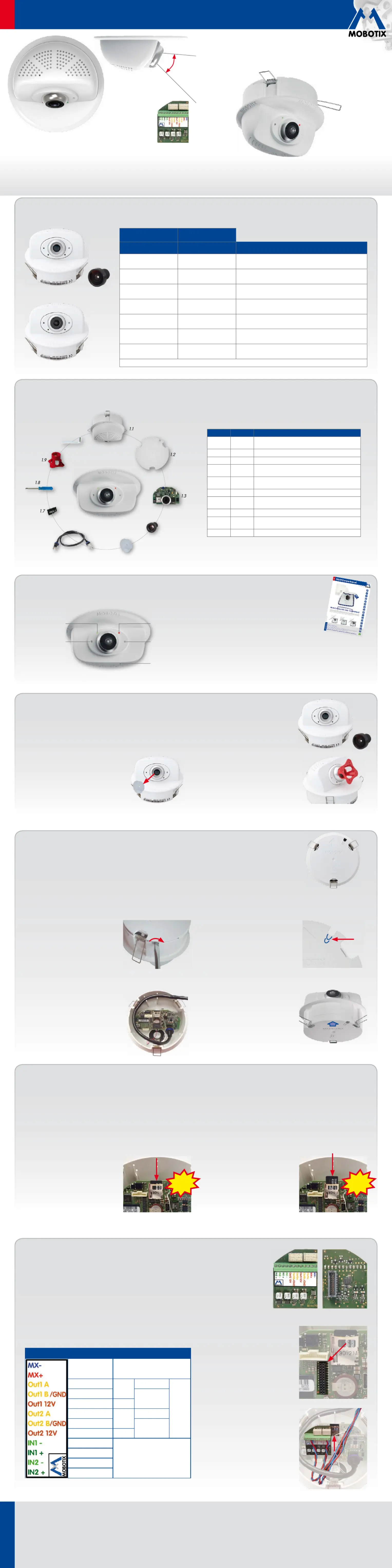
Quick InstallIndoor Camera p25
Security-Vision-Systems
32.356-001_EN_06/2015
MX-p25
www.mobotix.com
• Includes MxAnalytics video analysis tools out-of-the-box
• Recording on internal MicroSD card (SDXC)
• Signal Input/Output and MxBus via optional MX-Bus-IO-Module
• Optional audio version with microphone and speaker
• Sensors for temperature, illumination, shock detection integrated
• Installation is as simple as installing a ceiling spotlight
p25 Standard Delivery
1.6
1.10
1.4
1.5
ItemCountPart Name
1.11Housing with spring clips and tiltable camera
receptacle (installed)
1.21Back cover (installed)
1.31Main board with lens mount (installed)
1.41Lens (only installed in camera models listed in
«Variants of the p25»
)
1.51Blind cover (only when self-mounting the lens with
MX-p25-BOD1)
1.61Ethernet patch cable, 50cm/19.7in, black (installed)
1.71MicroSD card pre-installed (SDHC montiert, SDXC
supported)
1.81Flat-head screwdriver, blue
1.91Lens wrench red (only with MX-p25-BOD1 and
lenses to )D036D237
1.101Allen wrench 1.5mm
Removing/Installing the Back Cover
The steps listed below are only required if you need to access the inside of the camera housing.
Make sure the power
supply to the camera is disconnected before opening the housing!
Caution:In order to avoid damage from electrostatic discharge, you should touch a grounded device before opening
the housing of the camera (e.g., the blank metal at the back of a computer). This will remove any static electricity that
may have built up.
1. Remove the cover
Remove the back cover of the p25 by insert-
ing a flat-head screwdriver into one of the
slots at the side as shown in the figure and
turning it slightly. Repeat the process for
the two other slots and lift the back cover
from the housing.
2. Follow the procedures
Follow the procedures for the work inside
the housing as described in the sections
listed below:
•
➔ Inserting/Exchanging the SD Card
•
➔ Installing the MX-Bus-IO-Module
3. If required, enlarge the cable guide
If the cable guide is not large enough for
additional cables, enlarge the guide accord
-
ingly. Depending on the size required, break
out either one or two elements of the cable
guide using pliers (see blue markings in
the figure).
4. Attach back cover
Insert the back cover, so that the large arrow
(highlighted blue in the figure) is positioned
in the viewing direction of the camera. Make
sure the cables and wires are guided prop-
erly thought the cable guide, then carefully
press the back cover into the housing until
it clicks into place.
Installing the Lens (Only MX-p25-BOD1 Variant)
The steps listed below are only required if the p25 has been ordered with separate lens for self-mounting (see
«Variants
of the p25»
).
1. Remove the blind cover
Remove the blind cover that protects the
image sensor during shipping from the
lens mount.
2. Install the lens
Screw the lens into the lens mount. Depend-
ing on the physical length of the lens, you
can use your hand and then the red lens
wrench (item1.9). After initial operation of
the camera, remember to adjust the focus of
the lens (see
«Initial Operation of the p25»
).
+
Connecting the p25
MicrophoneReceptacle for
adjusting the
camera tilt
Recording
Screw for
locking the
camera tilt
Power/Status
For information on the p25, please see connecting
the
M25 Camera Manual
, section
«Network and
Power Connection, Additional Cables»
.
Regarding the of the p25, please initial operation
see the
M25 Camera Manual
in
Chapter 3, «Initial
Operation»
.
MOBOTIX 6MP camera for flexible use in indoor applications,
install as complete Indoor Camera p25 (Day or Night) with selected lenses
or as camera module p25 (Day or Night) with separate lens (MX-B036 to
MX-B237).
www.mobotix.com> Products> p25
Compact and Flexible Indoor Camera
for Ceilings
Inserting/Exchanging the SD Card
All camera models can use the integrated microSD card (SDXC) to record video data. In order to exchange the microSD card, please proceed as outlined
in the following instruction. For information on reliable SD cards, please see the MOBOTIX website www.mobotix.com> Support> MX Media Library>
Planning in the document
MicroSD Card Whitelist for MOBOTIX Cameras
.
When replacing the SD card, make sure that recording has been deactivated in the browser (
Admin Menu> Storage> Storage on External File Server/
Flash Device
; activate recording again in the same dialog). Follow the instructions in section
«Removing/Installing the Back Cover»
to access the inside
of the camera and to close it again after inserting the SD card.
1. Remove the SD card
If a microSD card has been installed, gently
press with your finger as indicated by the
arrow until you hear a
click
. Then release
the SD card. The card is protruding slightly
and can be easily removed.
2. Insert the SD card
Insert the microSD card and gently press
with your finger as indicated by the arrow
until you hear another
click
.
Make sure that the SD card is fully inserted.
Click!
Click!
Can be tilted vertically
from –5° to –45°.
MOBOTIX p25 (Day) with lens MX-B036
MX-p25-D036
Installing the MX-Bus-IO-Module
For the p25, you can use the optionally available MX-Bus-IO-Module to attach MxBus devices (e.g., an
MX-GPS-Box), to attach external sensors using the signal inputs and to switch other devices via the signal
outputs. To facilitate the installation of the module, you should attach the connection wires before inserting
the module.
Follow the instructions in section
«Removing/Installing the Back Cover»
to access the inside of the camera
and to close it again after inserting the module.
1. Attach the connection cables
Attach the connection cables as shown in the terminal connector overview.
Terminal Connectors
MxBus
connections
MxBus
Output1A
Relay
pot.-
free
–
Out-
puts
Output1B/GND
Output1
12V self-
powered
Output112V–
Output2A
Relay
pot.-
free
–
Output2B/GND
Output2
12V self-
powered
Output212V–
Output1–
Inputs
Output1+
Output2–
Output2+
2. Insert the MX-Bus-IO-Module
Hold the MX-Bus-IO-Module with attached
connection wires over the receptacle on the
main board (red arrow in figure).
Use one finger to carefully press the board
of the module onto the receptacle. Make
sure that the green terminal connector block
is pointing upward (towards the SD card,
see red arrow in figure below).
Make sure that the MX-Bus-IO-Module is
fully inserted.
Please also make sure that the connection
wires are guided through the housing without
tension and in a loop so that the cables
do not lift the module out of its receptacle
when adjusting the camera tilt (see figure).
MX-Bus-IO-Module
for MxBus modules and
signal inputs/outputs
(accessory)
Variants of the p25
MX-p25-DayMX-p25-Night
6MP (3072x2048)
Color
6MP (3072x2048)
Black&White
Variant
MX-p25-BOD1*MX-p25-BOD1-N*
p25 camera module, for lenses MX-B036 to MX-B237
(f/1.8, 103° to 15°, self-mounted*)
MX-p25-D016MX-p25-N016
p25 Hemispheric with Fisheye lens MX-B016
(f/2.0, 180° horiz. angle of view)
MX-p25-D036MX-p25-N036
p25 with ultra-wide-angle lens MX-B036
(f/1.8, 103° horiz. angle of view)
MX-p25-D061
Self-mounted* with
MX-p25-BOD1-N
p25 with wide-angle lens MX-B061
(f/1.8, 60° horiz. angle of view)
MX-p25-D079
Self-mounted* with
MX-p25-BOD1-N
p25 with standard lens MX-B079
(f/1.8, 45° horiz. angle of view)
MX-p25-D119
Self-mounted* with
MX-p25-BOD1-N
p25 with tele lens MX-B119
(f/1.8, 31° horiz. angle of view)
MX-p25-D237
Self-mounted* with
MX-p25-BOD1-N
p25 with distance tele lens MX-B237
(f/1.8, 15° horiz. angle of view)
*Requires focusing after self-mounting the lens (see
«Initial Operation of the p25»
)
MX-p25-D/N...
MX-p25-BOD1* + lens
+
Produktspecifikationer
| Varumärke: | Mobotix |
| Kategori: | övervakningskamera |
| Modell: | P25 |
| Videoformat som stöds: | H.265, M-JPEG, MxPEG |
| Maximal upplösning: | 3072 x 2048 pixlar |
| Antal kameror: | 1 |
| Zoomkapacitet: | Ja |
| Full HD: | Ja |
| Optisk sensorstorlek: | 1/1.8 " |
| Bildsensortyp: | CMOS |
| Digital zoom: | 8 x |
| Gränssnitt: | RJ-45 |
| Grafikupplösningar som stöds: | 3072 x 2048 |
| Modell: | IP-säkerhetskamera |
| USB-anslutning: | Ja |
| Progressiv skanning: | Ja |
| Temperatursensor: | Ja |
| Typ av minneskort: | MicroSD (TransFlash) |
| Produktens färg: | Vit |
| Inbyggd kortläsare: | Ja |
| Formfaktor: | Kupol-formad |
| Strömförbrukning (Power over Ethernet (PoE)): | 4 W |
| Typ av ethernet-gränssnitt: | Snabb Ethernet |
| Strömförsörjning via Ethernet (PoE) stöd: | Ja |
| Antal LAN (RJ-45) anslutningar: | 1 |
| Temperatur vid drift: | 0 - 40 ° C |
| Internationellt skydd (IP) kod: | IP20 |
| Video rörelsedetektor: | Ja |
| Kryptering/säkerhet: | HTTPS, SNMP |
| Kabel inkluderad: | LAN (RJ-45) |
| Placeringar som kan användas: | inomhus |
| Anslutningsteknologi: | Kabel |
| Monteringssätt: | Tak |
| Totalt megapixel: | 6 MP |
| Komprimeringsformat: | H.265, M-JPEG, MxPEG |
| Bildfrekvens: | 30 fps |
| Nätverksansluten (Ethernet): | Ja |
| Strömkälla av typen: | PoE |
| USB-port: | Ja |
| Kommunikationsstandarder: | IEEE 802.3af |
| PTZ-styrning: | Ja |
Behöver du hjälp?
Om du behöver hjälp med Mobotix P25 ställ en fråga nedan och andra användare kommer att svara dig
övervakningskamera Mobotix Manualer

13 Augusti 2025
10 Augusti 2025
10 Augusti 2025
10 Augusti 2025
10 Augusti 2025
10 Augusti 2025
10 Augusti 2025
10 Augusti 2025
10 Augusti 2025
10 Augusti 2025
övervakningskamera Manualer
Nyaste övervakningskamera Manualer
2 April 2026
2 April 2026
1 April 2026
1 April 2026
1 April 2026
31 Mars 2026
31 Mars 2026
31 Mars 2026
30 Mars 2026
30 Mars 2026