Optex CKB-312 Bruksanvisning
Optex Inte kategoriserad CKB-312
Läs gratis den bruksanvisning för Optex CKB-312 (2 sidor) i kategorin Inte kategoriserad. Guiden har ansetts hjälpsam av 42 personer och har ett genomsnittsbetyg på 4.2 stjärnor baserat på 4 recensioner. Har du en fråga om Optex CKB-312 eller vill du ställa frågor till andra användare av produkten? Ställ en fråga
Sida 1/2
CKB312
Visual Verification Bridge
Setup your CHeKT Dealer Portal
Before getting started with CHeKT, you will need
access to a CHeKT dealer web portal. Access to this
portal allows you to install and manage
all your CHeKT devices. If you do not
have an account, please request a
dealer account by visiting:
www.chekt.com/registration
1.Connecting Power
Connect 12v of DC power to the power input on the terminal block included in the package. You can power the Bridge using the 12-
volt power output from an alarm panel. Power status LED is either red or green depending on the armed state, when the unit is on.
A standard 12vDC transformer can also power the Bridge.
•12v DC Power Requirement
•Peak 800mA power draw per unit
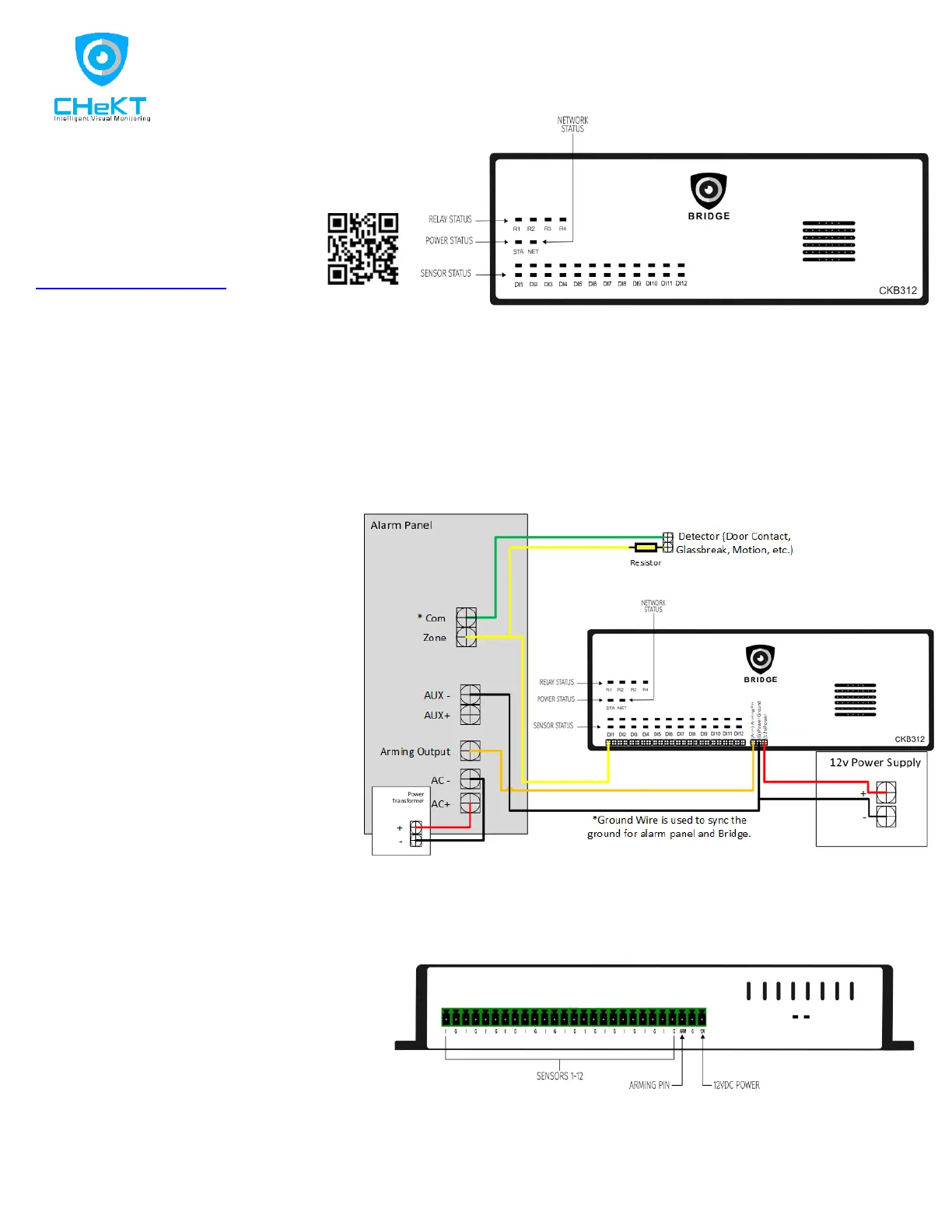
2.Wiring Input Triggers
The Bridge can support triggered events from cameras with edge-based analytics or a physical input trigger from a sensor or relay.
There are 12 physical, digital input zones on the CKB312 Bridge. Each of these zones are programmed to operate independently,
but all are a part of a common ground.If you are wiring the Bridge with an existing alarm panel, the alarm zones connect to these
inputs, as shown in Figure 2 below. The Bridge works with any device that can trip the alarm input of the Bridge. The alarm zones
each consist of an (I)nput, (G)round*.
If the Bridge shares a common ground with the
alarm panel, then (G) is not needed. Simply
wire from one of Digital Inputs of the Bridge to
the zone terminal of the alarm panel, as shown
in Figure 2. Repeat this for each alarm zone
going through the Bridge. Whenever that
detector is triggered, the voltage changes on
this loop, signaling the Bridge to create a video
event for the camera assigned to that Digital
Input Zone. The alarm panel transmits the
alarm signal as programmed in your alarm
panel and simultaneously, the Bridge uploads
video to the CHeKT web portal.
If you are using a relay to trigger one of the
Digital Input zones, then use both the (I) and
(G) terminals.
If the Bridge is powered by an external source to the alarm panel, a common ground between the power supply, alarm panel and
bridge is required. *All ground terminals on the Bridge are common.
Using the CHeKT Dealer Portal, the installer must set the appropriate voltage ranges in the Bridge programming for both the alarm
and normal conditions. The 12 Digital Input LED lights on the Bridge are red when the Digital Input is in “Alarm” and are off when
the input is “Normal.” Each alarm panel
manufacturer has published values for normal and
alarm voltage. Once the wiring is complete,
technicians are advised to test the functionality of
each detector by activating both the Bridge and the
alarm panel.
What happens if CHeKT Bridge is powered off?
The alarm detection devices connected to the Bridge still function even if the Bridge is powered down; however, the Bridge will not
communicate alarm and video events.
Visual Verification Bridge Installation Guide
CKB312
Figure 2
Figure 1
Figure 3
Produktspecifikationer
| Varumärke: | Optex |
| Kategori: | Inte kategoriserad |
| Modell: | CKB-312 |
Behöver du hjälp?
Om du behöver hjälp med Optex CKB-312 ställ en fråga nedan och andra användare kommer att svara dig
Inte kategoriserad Optex Manualer

21 December 2024
6 December 2024
6 December 2024
6 December 2024
6 December 2024
6 December 2024
6 December 2024
2 Oktober 2024
26 September 2024
25 September 2024
Inte kategoriserad Manualer
Nyaste Inte kategoriserad Manualer
9 April 2025
9 April 2025
9 April 2025
9 April 2025
9 April 2025
9 April 2025
9 April 2025
9 April 2025
9 April 2025
9 April 2025