PCE Instruments PCE-VT 204 Bruksanvisning
PCE Instruments Mätutrustning PCE-VT 204
Läs gratis den bruksanvisning för PCE Instruments PCE-VT 204 (30 sidor) i kategorin Mätutrustning. Guiden har ansetts hjälpsam av 26 personer och har ett genomsnittsbetyg på 4.6 stjärnor baserat på 6 recensioner. Har du en fråga om PCE Instruments PCE-VT 204 eller vill du ställa frågor till andra användare av produkten? Ställ en fråga
Sida 1/30
Manual
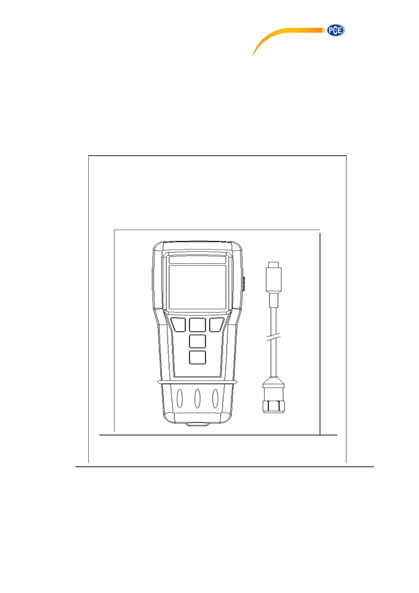
Vibration Analyser
PCE-VT 204
PCE Americas Inc.
711 Commerce Way
Suite 8
Jupiter
FL-33458
USA
From outside US: +1
Tel: (561) 320-9162
Fax: (561) 320-9176
www.pce-instruments.com/english
www.pce-instruments.com
PCE Instruments UK Ltd.
Units 12/13
Southpoint Business Park
Ensign way
Hampshire / Southampton
United Kingdom, SO31 4RF
From outside UK: +44
Tel: (0) 2380 98703 0
Fax: (0) 2380 98703 9
Produktspecifikationer
| Varumärke: | PCE Instruments |
| Kategori: | Mätutrustning |
| Modell: | PCE-VT 204 |
Behöver du hjälp?
Om du behöver hjälp med PCE Instruments PCE-VT 204 ställ en fråga nedan och andra användare kommer att svara dig
Mätutrustning PCE Instruments Manualer

29 Mars 2025
28 Mars 2025
28 Mars 2025
28 Mars 2025
28 Mars 2025
28 Mars 2025
28 Mars 2025
28 Mars 2025
28 Mars 2025
28 Mars 2025
Mätutrustning Manualer
Nyaste Mätutrustning Manualer
3 April 2025
3 April 2025
3 April 2025
3 April 2025
3 April 2025
3 April 2025
3 April 2025
3 April 2025
3 April 2025
3 April 2025