Rane GQ 15 Bruksanvisning
Rane blandningskonsoler GQ 15
Läs gratis den bruksanvisning för Rane GQ 15 (4 sidor) i kategorin blandningskonsoler. Guiden har ansetts hjälpsam av 14 personer och har ett genomsnittsbetyg på 4.0 stjärnor baserat på 5 recensioner. Har du en fråga om Rane GQ 15 eller vill du ställa frågor till andra användare av produkten? Ställ en fråga
Sida 1/4
OPERATING / SERVICE MANUAL
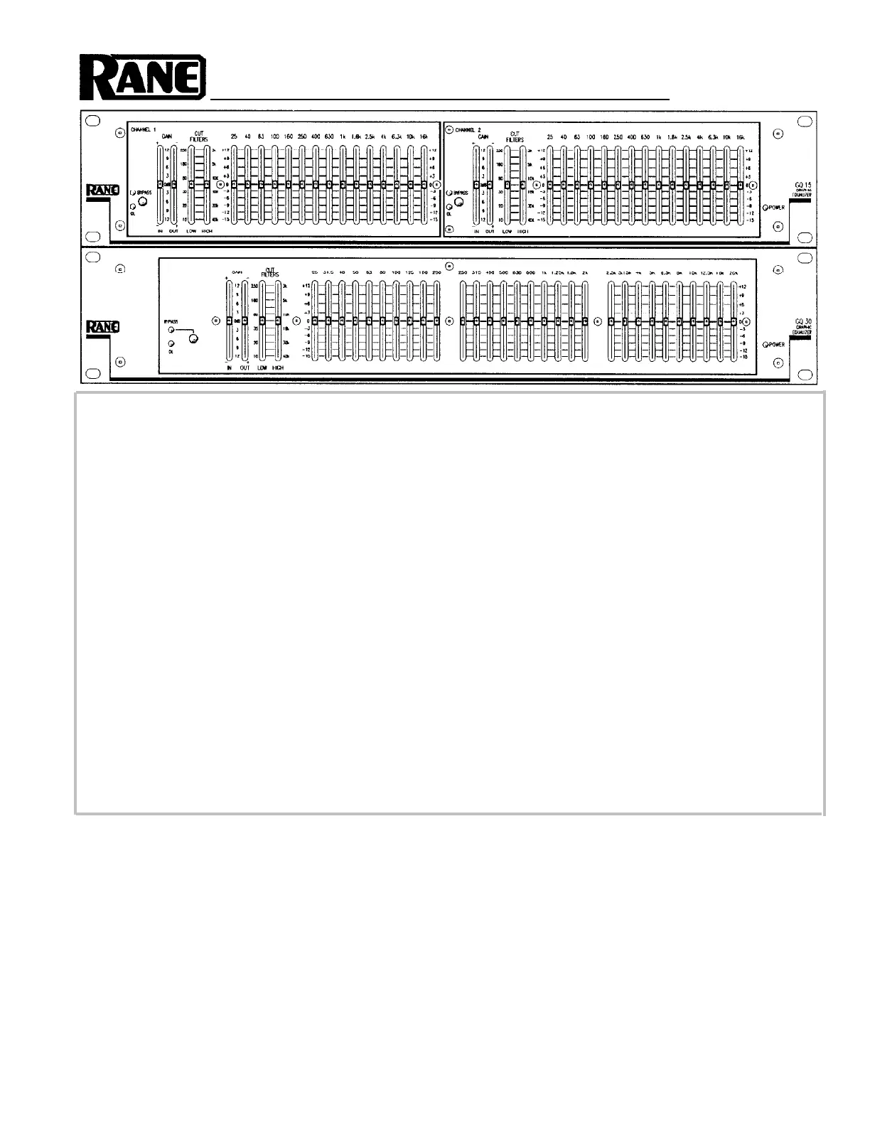
GQ 15/30
QUICK START
This section is for all of us who hate to read manuals. For those of us who want to just do it. But this attitude inevitably gets
us into trouble. So in the interest of keeping you out of trouble, we present this abbreviated overview of your equalizer.
Please read at least this much. Thank you.
Hook-up is intuitive. Just follow the silkscreened instructions on the rear of the unit. All three Inputs are wired in parallel
(they do not sum); and all three Outputs are wired in parallel. Use any ONE Input and any or all Outputs. Using the GQ
15/GQ 30 in an Insert Loop of a mixer is extremely easy. Simply connect them together using a single stereo cable (1/4"
TRS) between the mixer’s Insert Loop and the GQ 15/GQ 30’sPATCH I/O jack. This jack is wired for the tip = send,
ring = return convention used by many mixer manufacturers. CAUTION: USE EITHER THE PATCH I/O OR THE
INPUT AND OUTPUT CONNECTORS — DO NOT USE BOTH.
Anyone familiar with other graphic equalizers finds the GQ 15/GQ 30 just as familiar.
Setting theIN and OUT GAIN controls to the same physical positions gives unity gain through the equalizer. That is,
moving both slider handles together (keeping them aligned) always maintains overall unity gain from input to output. Many
strange gain structure conditions may be handled with these controls. FOR BEST NOISE PERFORMANCE ALWAYS
POSITION BOTH CONTROLS AS FAR TOWARD THE TOP OF THE UNIT AS POSSIBLE WITHOUT LIGHTING
THE OL INDICATORS. See the Operating Instructions on the back page for more information. Setting curves is as easy as
it is on all Rane graphics thanks to our unique interpolating constant-Q circuitry. For more information on setting up your
curves correctly, again, see the back page.
Set theCUT FILTERScontrols for the desired low and high cut frequencies. Sliding them fully downward essentially
defeats these functions.
NEVER CONNECT ANYTHING EXCEPT AN APPROVED RANE POWER SUPPLY TO THE RED THING THAT
LOOKS LIKE A TELEPHONE JACK ON THE REAR OF THE UNIT. This is an AC input and requires special attention
if you do not have a power supply EXACTLY like the one originally packed with your unit. See the full explanation of the
power supply requirements elsewhere in this manual.
continued
SYSTEM CONNECTION
When first connecting the GQ 15/GQ 30 to other components, LEAVE THE POWER SUPPLY FOR LAST. This gives
you a chance to make mistakes and correct them without damaging your fragile speakers, ears and nerves.
INPUTS. All three inputs are wired in parallel and are actively balanced (true instrumentation amplifiers). Each works
equally well. Choose strictly from a favorite hardware point-of-view, there will be no performance trade-offs. The wiring
convention adheres to American, British and International standards of pin 2, +, or tip being hot, pin 3, –, or ring being
return, and pin 1, COMMON GND, or sleeve being signal ground. Unbalanced operation involves using only pin 2, + , or
tip as signal and pin 1, COMMON GND, or sleeve as ground. It is not necessary to short any terminals or pins to any others.
Due to the true instrumentation nature of the inputs, there is no gain reduction if pin 3, or –, is left open; however, if pin 3
gets shorted, it won’t hurt anything either. Use pin 1, the shell, or the COMMON GND point on the barrier strip for shield
ground. (See Rane Note 110 for further information).
Produktspecifikationer
| Varumärke: | Rane |
| Kategori: | blandningskonsoler |
| Modell: | GQ 15 |
Behöver du hjälp?
Om du behöver hjälp med Rane GQ 15 ställ en fråga nedan och andra användare kommer att svara dig
blandningskonsoler Rane Manualer

12 September 2025
11 September 2025
10 September 2025
10 September 2025
10 September 2025
10 September 2025
10 September 2025
10 September 2025
10 September 2025
10 September 2025
blandningskonsoler Manualer
Nyaste blandningskonsoler Manualer
3 April 2026
2 April 2026
31 Mars 2026
29 Mars 2026
28 Mars 2026
19 Mars 2026
18 Mars 2026
14 Mars 2026
10 Mars 2026
25 Februari 2026