Speco Technologies P24S26G2 Bruksanvisning
Speco Technologies ej kategoriserat P24S26G2
Läs gratis den bruksanvisning för Speco Technologies P24S26G2 (1 sidor) i kategorin ej kategoriserat. Guiden har ansetts hjälpsam av 35 personer och har ett genomsnittsbetyg på 5.0 stjärnor baserat på 8 recensioner. Har du en fråga om Speco Technologies P24S26G2 eller vill du ställa frågor till andra användare av produkten? Ställ en fråga
Sida 1/1
8 Indicator Definition
Indicator LightStateMeaning
※This function is applicable to PoE switches,not applicable to non-PoE switches.
* Please contact Speco Technologies technical support @ 1-800-645-5516
if you have any questions.
DIPFunctionDescription
1
2
3
4
PoE Watchdog
Link Extension
Port Isolation
Storm Control
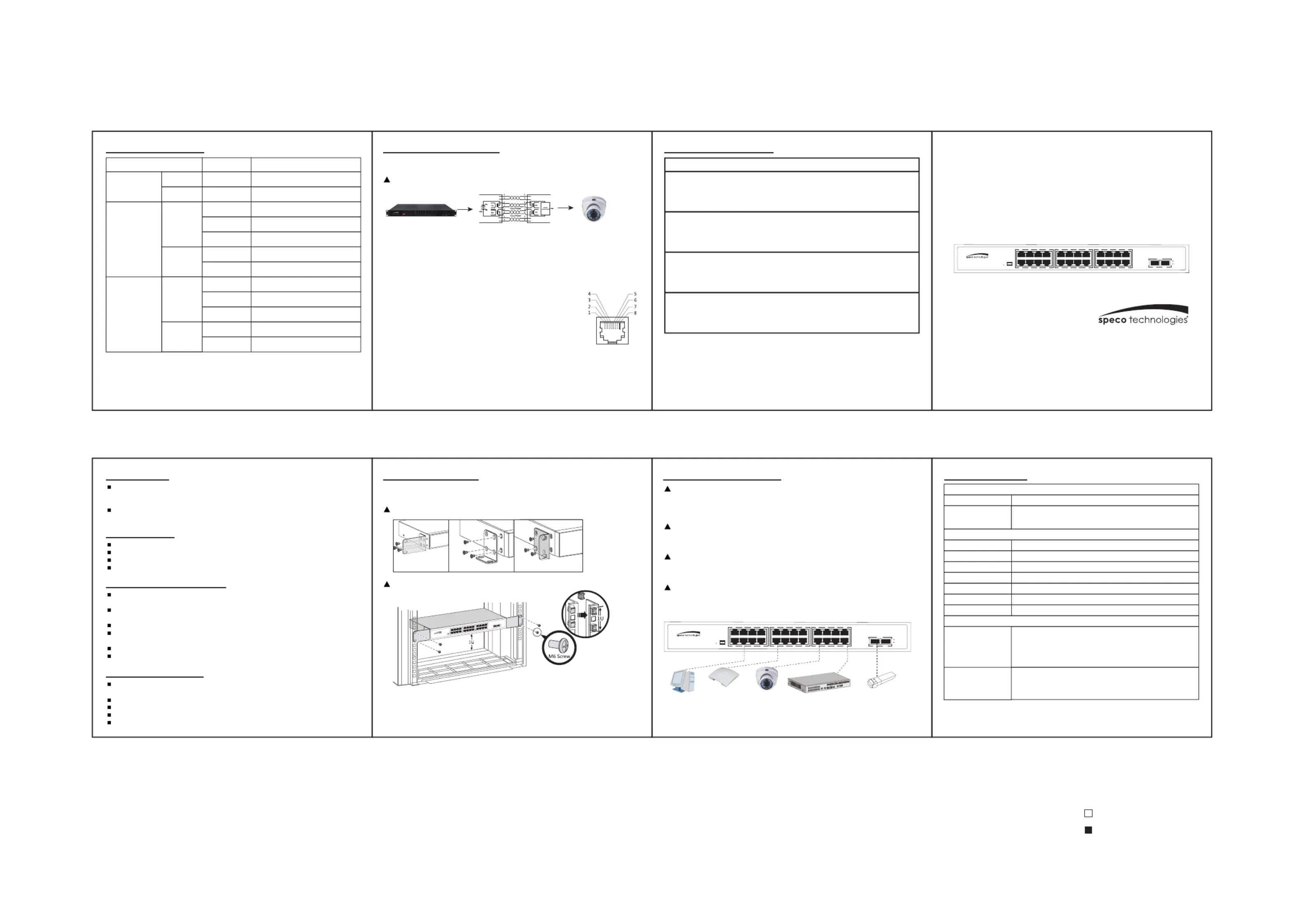
1 Description
9 PoE Powered Function
5 Switch Installation7 Technical Spec.
10 States of DIP Switch
Standard PoE Power Supply
Mounting Ear Installation
Network Cable
Grounding
Rack Mount Installation
PoE SwitchPoE Camera12/36 is the power
supply and data pin
1.Standard PoE power supply includes: protocol detection, power pin sequence
Detection, power output, abnormal protection, link abnormal monitoring
2.The PoE power supply protocol includes: IEEE802.3af(15.4W), IEEE802.3at(30W)
3.The standard PoE power pin sequence is 12+/36-,and the
passive PoE power pin sequence is 45+/78-
4.The standard POE switches can automatically detect and supply
power to the PDs that meet the standard,non-POE devices are not
powered and only transmit data
5. PoE Watchdog
When the switch port communication fails, the corresponding port
POE will automatically detect and restart, restore network
communication by itself, and reduce manual intervention and maintenance.
When the switch port communication fails,
the corresponding port POE will
automatically detect and restart, restore
network communication by itself.
1-24 ports PoE power supply and data
transmission distance can be extended to
250 meters, the transmission rate
becomes 10M
PoE ports (1-24) of the switch cannot
communicate with each other, and can only
communicate with uplink ports
Enables the switch to monitor traffic levels
and to drop broadcast, multicast, and
unknown unicast packets when a specified
traffic level is exceeded.
Switches support a variety of installation methods, desktop, wall mounted, rack mount,
please install according to the actual environmental requirements.
10Base-T: Cat3, 4, 5 or above UTP(≤250m).
100Base-TX: Cat5 or above UTP(≤150m) .
1000Base-TX: Cat5 or above UTP(≤100m).
Ensure that the grounding screw of the equipment is effectively grounded to protect
the safety of the equipment.
Optical Fiber
1.Optical fibers must be used with the optical module.
2.Fiber bending radius must not be less than 40mm.
Power Cable
1.Distance between power cable and network cable should be more than 10cm.
2.The AC power please use the local AC power cable.
1. Install 4 floating screws on the front hole bar of the cabinet on each side.
2. Load the equipment into the cabinet.
3. Use M6 screws to secure the equipment with the cabinet/rack.
4. Install earth wire to earth connection point.
The products described in this manual, incduding but not limited to the illustrated
products, please refer to the actual product purchased.If any changes on product
appearance, please refer to the official product information.
PoE switch and ethernet switch installation methods are the same, the actual use
environment and method that depends on the specific product requirement.
User Manual
6 Connecting Equipment
2 Packing List
Switch(Specific model See the product label for more details).
Power Cable(The default is pluggable or a power cable with built-in power module).
Brackets, Screw(Rack type standard).
User manual,Certification.
3 Installation Precautions
Do not install the equipment in the environment of seepage, drip or condensation
easily,otherwise the equipment might burn out.
Please ensure the environment where the equipment is installed is well ventilated,
and forbidden to block the cooling holes.
Do not install the equipment in a high density dust environment.
If rack switches are in a natural heat dissipation environment, please ensure the
separation distance exceeds 1U.
Do not aerial cabling outdoor, otherwise the equipment is prone to lightning strike.
Using temperature and humidity depend on the descriptions of the specific product.
4 Safety Precautions
Do not look directly at the optical port to prevent the laser beam from burning your
eyes.
Do not install the power cord with power on to avoid personal injury.
Do not supply power before equipment installation and wiring.
ESD protection is necessary during the installation and maintenance of equipment.
Do not place objects on the device.
24 PortWall Mounted1U Rack
尺寸:90x360mm
印刷:黑白印刷
纸张:铜版纸80g
字体:Arial
C0 M0 Y0 K0
C0 M0 Y0 K100
P24S26G2 26-Port Gigabit Switch
24-PoE Ports and 2 SFP Uplink
ComputerCameraSwitchOptical ModuleWireless AP
I/O Interface
Performance
Mechanical
PowerInput AC 100-240V, 50/60Hz
52Gbps
38.6Mpps
4.1Mb
8K
10Kbytes
Store and forward
100,000 hours
Product Dimension (LxWxH): 440x280x44mm
Package Dimension (LxWxH): 525x395x95mm
N.W: 1.8kg
G.W: 4.5kg
Carton MEAS: 540x495x410mm
Packing Qty: 5 pieces
Packing Weight: 25.7kg
Fixed Port
Switching Capacity
Throughput
Packet Buffer
MAC Address
Jumbo Frame
Transfer Mode
MTBF
Structure Size
Packing Info
24x10/100/1000M PoE Ports
2x1000M SFP Uplink ports
No power input
The device operates normally
Port connected
Port not connected
1000M connected
10/100M connected
Port connected
Port not connected
1000M connected
10/100M connected
Port connected, and Data sending
or receiving
Port connected, and Data sending
or receiving
No power
Power on
on
off
Flash
on
off
on
off
Flash
on
off
Off
On
PWR
1000M optical
port
Green
Light
Link/act
Yellow
Light
Speed
Green
Light
Link/act
Yellow
Light
Speed
10/100/1000M
Ethernet port
Gigabit PoE Unmanaged Switch
PWR
1357
2468
9111315
10121416
17192123
18202224
Uplink
25
25
26
26
1 2 3 4
ON
Gigabit PoE Unmanaged Switch
PWR
1357
2468
9111315
10121416
17192123
18202422
Uplink
25
25
26
26
1 2 3 4
ON
Gigabit PoE Unmanaged Switch
PWR
1357
2468
9111315
10121416
17192123
18202224
Uplink
25
25
26
26
1 2 3 4
ON
Produktspecifikationer
| Varumärke: | Speco Technologies |
| Kategori: | ej kategoriserat |
| Modell: | P24S26G2 |
Behöver du hjälp?
Om du behöver hjälp med Speco Technologies P24S26G2 ställ en fråga nedan och andra användare kommer att svara dig
ej kategoriserat Speco Technologies Manualer

18 Augusti 2025
17 Augusti 2025
17 Augusti 2025
17 Augusti 2025
16 Augusti 2025
15 Augusti 2025
15 Augusti 2025
15 Augusti 2025
15 Augusti 2025
15 Augusti 2025
ej kategoriserat Manualer
Nyaste ej kategoriserat Manualer
3 April 2026
3 April 2026
3 April 2026
3 April 2026
3 April 2026
3 April 2026
3 April 2026
3 April 2026
3 April 2026