Supermicro SuperServer 5019A-FTN4 Bruksanvisning
Supermicro Inte kategoriserad SuperServer 5019A-FTN4
Läs gratis den bruksanvisning för Supermicro SuperServer 5019A-FTN4 (116 sidor) i kategorin Inte kategoriserad. Guiden har ansetts hjälpsam av 17 personer och har ett genomsnittsbetyg på 4.6 stjärnor baserat på 9 recensioner. Har du en fråga om Supermicro SuperServer 5019A-FTN4 eller vill du ställa frågor till andra användare av produkten? Ställ en fråga
Sida 1/116
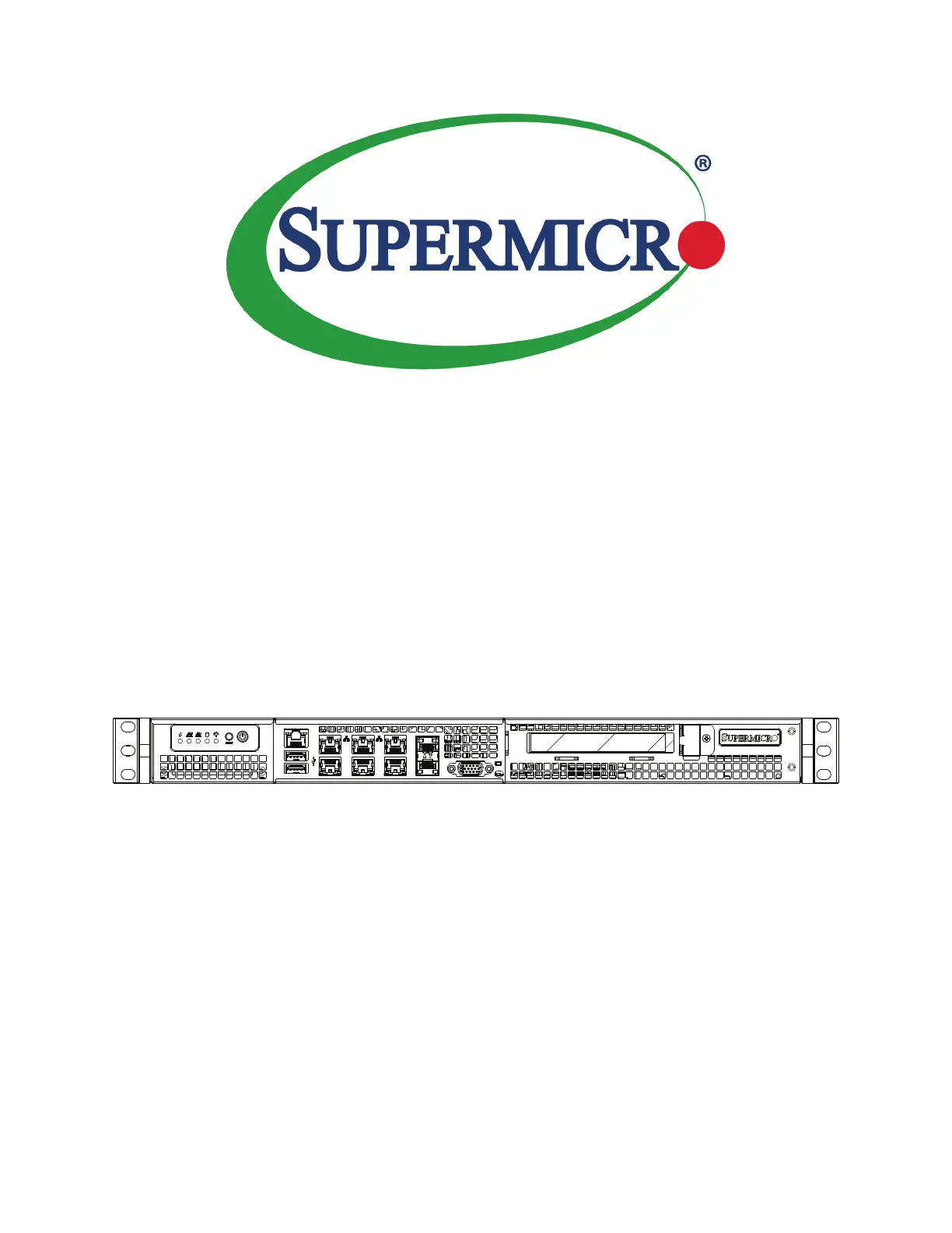
USER’S MANUAL
Revision 1.0
SuperServer
®
5019A-FTN4
Produktspecifikationer
| Varumärke: | Supermicro |
| Kategori: | Inte kategoriserad |
| Modell: | SuperServer 5019A-FTN4 |
| Bredd: | 437 mm |
| Djup: | 249 mm |
| Höjd: | 43 mm |
| Strömförsörjning: | 200 W |
| Processorfamilj: | Intel |
| Maximalt internminne: | 128 GB |
| Minnesspänning: | 1.2 V |
| Antal processorer som stöds: | 1 |
| Antal lagringsenheter som stöds: | 4 |
| Minnestyper som stöds: | DDR4-SDRAM |
| BIOS-typ: | UEFI AMI |
| ACPI-version: | 5.0 |
| Produktens färg: | Svart |
| Inbyggd processor: | Nej |
| Typ av ethernet-gränssnitt: | Fast Ethernet, Gigabit Ethernet |
| Datahastighet för Ethernet-LAN: | 10,100,1000 Mbit/s |
| Antal LAN (RJ-45) anslutningar: | 4 |
| Temperatur vid drift: | 0 - 40 ° C |
| Temperaturintervall (förvaring): | -40 - 70 ° C |
| Intervall för relativ operativ luftfuktighet: | 8 - 90 % |
| Fuktighet (förvaring): | 5 - 95 % |
| processorsockel: | BGA 1310 |
| Seriella portar: | 1 |
| Hållbarhetscertifiering: | RoHS |
| AC-inspänning: | 100 - 240 V |
| Fläktdiameter: | 40 mm |
| Nätverksansluten (Ethernet): | Ja |
| Växelström Frekvens: | 50 - 60 hz |
| BIOS-funktioner: | Plug & Play, SMBIOS 2.7.1, UEFI |
| Antal USB 2.0 anslutningar: | 2 |
| Moderkortets chipset: | Intel® SoC |
| Harmonized System (HS)-kod: | 84714100 |
| Antal fläktar: | 2 fläkt/-ar |
| Kvalitet på VGA (D-Sub) porten: | 1 |
| PCI Express-kortplatser version: | 3.0 |
| Ombord grafikkort modell: | Aspeed AST2400 |
| Storlekar som stöds på lagringsenhet: | 2.5, 3.5 " |
| Koppar Ethernet-kablar teknik: | 10BASE-T, 100BASE-TX, 1000BASE-T |
| Lagringsenhetsgränssnitt som stöds: | Serial ATA III |
| ECC: | Ja |
| Chassityp: | Rack (1U) |
| Antalet DIMM-platser: | 4 |
| Som stöds DIMM-modul kapacitet: | 4GB, 8GB, 16GB, 32GB |
| Hårddisk hot swap: | Ja |
| PCI Express x4 platser: | 1 |
| Maximalt RDIMM minne: | 128 GB |
| Maximalt UDIMM minne: | 64 GB |
| Stöd för RDIMM klockfrekvenser: | 1600,1866,2133,2400 MHz |
| IPMI LAN (RJ-45)-port: | Ja |
| Likspänning ut (+12 V): | 16 A |
| Likspänning ut (+5 V): | 8 A |
Behöver du hjälp?
Om du behöver hjälp med Supermicro SuperServer 5019A-FTN4 ställ en fråga nedan och andra användare kommer att svara dig
Inte kategoriserad Supermicro Manualer

1 April 2025
1 April 2025
31 Januari 2025
31 Januari 2025
31 Januari 2025
31 Januari 2025
9 Januari 2025
4 Januari 2025
29 December 2024
29 December 2024
Inte kategoriserad Manualer
Nyaste Inte kategoriserad Manualer
9 April 2025
9 April 2025
9 April 2025
9 April 2025
9 April 2025
9 April 2025
9 April 2025
9 April 2025
9 April 2025
9 April 2025