Supermicro SuperServer SYS-510T-ML Bruksanvisning
Supermicro Server SuperServer SYS-510T-ML
Läs gratis den bruksanvisning för Supermicro SuperServer SYS-510T-ML (95 sidor) i kategorin Server. Guiden har ansetts hjälpsam av 26 personer och har ett genomsnittsbetyg på 4.3 stjärnor baserat på 6 recensioner. Har du en fråga om Supermicro SuperServer SYS-510T-ML eller vill du ställa frågor till andra användare av produkten? Ställ en fråga
Sida 1/95
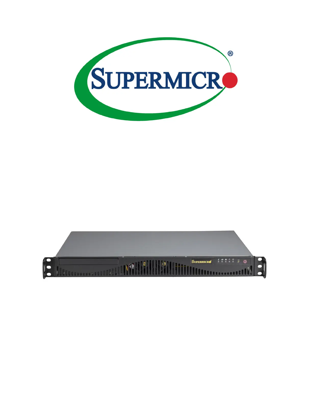
USER’S MANUAL
Revision 1.0
SuperServer
®
510T-ML
Produktspecifikationer
| Varumärke: | Supermicro |
| Kategori: | Server |
| Modell: | SuperServer SYS-510T-ML |
Behöver du hjälp?
Om du behöver hjälp med Supermicro SuperServer SYS-510T-ML ställ en fråga nedan och andra användare kommer att svara dig
Server Supermicro Manualer

16 Februari 2026
31 Januari 2026
31 Januari 2026
30 Januari 2026
26 Januari 2026
13 September 2025
13 September 2025
12 September 2025
12 September 2025
12 September 2025
Server Manualer
Nyaste Server Manualer
1 April 2026
24 Mars 2026
19 Mars 2026
3 Februari 2026
20 Oktober 2025
19 Oktober 2025
19 Oktober 2025
19 Oktober 2025
19 Oktober 2025
19 Oktober 2025