Supermicro SuperStorage 2029P-DN2R24L Bruksanvisning
Supermicro Inte kategoriserad SuperStorage 2029P-DN2R24L
Läs gratis den bruksanvisning för Supermicro SuperStorage 2029P-DN2R24L (22 sidor) i kategorin Inte kategoriserad. Guiden har ansetts hjälpsam av 20 personer och har ett genomsnittsbetyg på 4.2 stjärnor baserat på 8 recensioner. Har du en fråga om Supermicro SuperStorage 2029P-DN2R24L eller vill du ställa frågor till andra användare av produkten? Ställ en fråga
Sida 1/22
USER’S MANUAL
Revision 1.0b
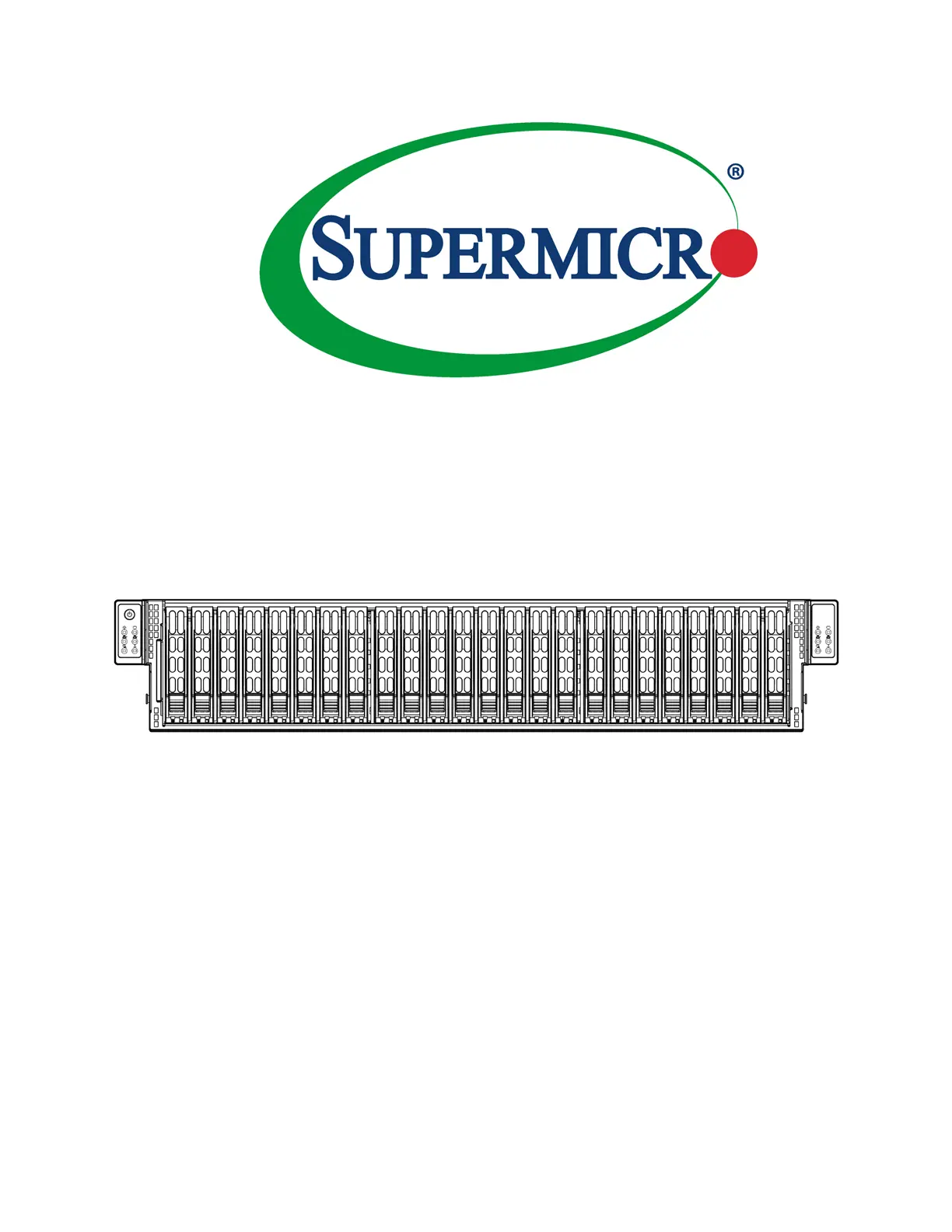
SuperStorage Server
2029P-DN2R24L
Produktspecifikationer
| Varumärke: | Supermicro |
| Kategori: | Inte kategoriserad |
| Modell: | SuperStorage 2029P-DN2R24L |
| Vikt: | 30400 g |
| Bredd: | 437 mm |
| Djup: | 650 mm |
| Höjd: | 89 mm |
| Strömförsörjning: | 2000 W |
| LED-indikatorer: | Ja |
| Processorfamilj: | Intel® Xeon® Scalable |
| Maximalt internminne: | 3000 GB |
| Intel® Optane™ Memory Ready: | Ja |
| Antal processorer som stöds: | 2 |
| Antal lagringsenheter som stöds: | 24 |
| Minnestyper som stöds: | DDR4-SDRAM |
| BIOS-typ: | UEFI AMI |
| Produktens färg: | Svart |
| processortillverkare: | Intel |
| Inbyggd processor: | Nej |
| Typ av ethernet-gränssnitt: | 10 Gigabit Ethernet |
| Datahastighet för Ethernet-LAN: | 10000 Mbit/s |
| Antal LAN (RJ-45) anslutningar: | 6 |
| Temperatur vid drift: | 10 - 35 ° C |
| Temperaturintervall (förvaring): | -40 - 60 ° C |
| Intervall för relativ operativ luftfuktighet: | 8 - 90 % |
| Fuktighet (förvaring): | 5 - 95 % |
| processorsockel: | LGA 3647 (Socket P) |
| Hållbarhetscertifiering: | RoHS |
| AC-inspänning: | 100 - 240 V |
| Nätverksansluten (Ethernet): | Ja |
| Växelström Frekvens: | 50 - 60 hz |
| På / av-knapp: | Ja |
| RAID-nivåer: | 0, 1 |
| Antal USB 3.2 Gen 1 (3.1 Gen 1) typ A-portar: | 4 |
| Moderkortets chipset: | Intel® C624 |
| Ingående ström: | 9.5 - 12.5 A |
| Systembuss, hastighet: | 10.4 GT/s |
| PCI Express-kortplatser version: | 3.0 |
| Ombord grafikkort modell: | Aspeed AST2500 |
| Storlekar som stöds på lagringsenhet: | 2.5 " |
| Kylning typ: | Aktiv |
| Stöd för redundant strömförsörjning (RPS): | Ja |
| ECC: | Ja |
| Chassityp: | Rack (2U) |
| Antal 2,5 "vikar: | 24 |
| Antalet DIMM-platser: | 12 |
| Hårddisk hot swap: | Ja |
| Antal COM portar: | 4 |
| 80 plus-certifiering: | 80 PLUS Titanium |
| PC hälsoövervakning: | CPU, FAN, Temperature |
| Maximalt RDIMM minne: | 3000 GB |
| Stöd för RDIMM klockfrekvenser: | 2133,2400,2666,2933 MHz |
| IPMI LAN (RJ-45)-port: | Ja |
| Likspänning ut (+12 V): | 166.7 A |
Behöver du hjälp?
Om du behöver hjälp med Supermicro SuperStorage 2029P-DN2R24L ställ en fråga nedan och andra användare kommer att svara dig
Inte kategoriserad Supermicro Manualer

1 April 2025
1 April 2025
31 Januari 2025
31 Januari 2025
31 Januari 2025
31 Januari 2025
9 Januari 2025
4 Januari 2025
29 December 2024
29 December 2024
Inte kategoriserad Manualer
Nyaste Inte kategoriserad Manualer
9 April 2025
9 April 2025
9 April 2025
9 April 2025
9 April 2025
9 April 2025
9 April 2025
9 April 2025
9 April 2025
9 April 2025