Texas Instruments LMR66410 Bruksanvisning
Texas Instruments ej kategoriserat LMR66410
Läs gratis den bruksanvisning för Texas Instruments LMR66410 (50 sidor) i kategorin ej kategoriserat. Guiden har ansetts hjälpsam av 7 personer och har ett genomsnittsbetyg på 4.8 stjärnor baserat på 5 recensioner. Har du en fråga om Texas Instruments LMR66410 eller vill du ställa frågor till andra användare av produkten? Ställ en fråga
Sida 1/50
LMR664x0 36-V, 1-A, 2-A, and 3-A, Ultra-Small, Synchronous Step-Down Converter
1 Features
•Functional Safety-Capable
–Documentation available to aid functional safety
system design
•Designed for industrial applications:
–Junction temperature range –40°C to +150°C
–NC pin between critical pins for better reliability
–Best in-class pin FMEA
–Input transient protection up to 42 V
–Wide input voltage range after start-up: 2.7 V
(falling threshold) to 36 V
–Adjustable output up to 95% of V
IN
, 3.3-V, and
5-V fixed V
OUT
options available
•Optimized for low EMI requirements:
–Dual random spread spectrum reduces peak
emissions
–Enhanced HotRod
™
QFN package minimizes
switch node ringing
•Greater than 85% efficiency at 1 mA
•Miniature design size and low component cost:
–2.6-mm × 2.6-mm enhanced HotRod QFN
package with wettable flanks
–Internal control loop compensation
2 Applications
•Factory automation: PLC, DCS, and PAC
•Test and measurement
•Medical
•Aerospace and defense
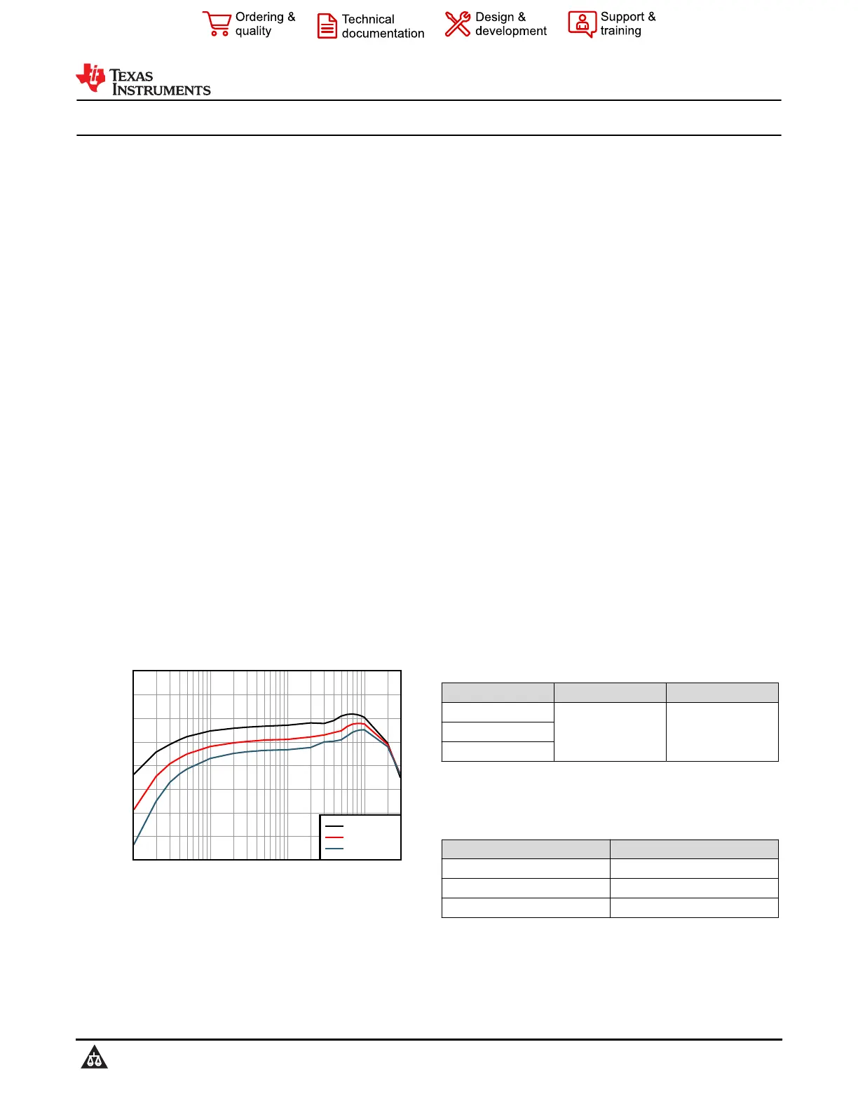
Output Current (A)
Efficiency (%)
0.0010.010.113
80
82.5
85
87.5
90
92.5
95
97.5
100
VIN = 12 V
VIN = 18 V
VIN = 24 V
Efficiency: V
OUT
= 5 V (Fixed), 400 kHz
3 Description
The LMR664x0 is a small 36-V, 3-A (available in 2-
A and 1-A variants) synchronous step-down DC/DC
converter in an enhanced HotRod QFN package.
This easy-to-use converter supports a wide input
voltage range of 2.7 V to 36 V (after start-up or after
operating) with transients up to 42 V.
The LMR664x0 is specifically designed to meet low
standby power requirements for always-on, industrial
applications. Auto mode enables frequency foldback
when operating at light loads, allowing an unloaded
typical current consumption of 1.5 µA at 13.5 V
IN
and high light load efficiency. A seamless transition
between PWM and PFM modes along with very
low MOSFET ON resistances makes sure there is
exceptional efficiency across the entire load range.
The control architecture (peak current mode) and
feature set are optimized for an ultra-small design
size with minimal output capacitance. The device
minimizes input filter size by using dual-random
spread spectrum (DRSS), a low-EMI enhanced
HotRod QFN package, and an optimized pin-out. The
MODE/SYNC and RT pin variants can be used to set
or synchronize the frequency to avoid noise sensitive
frequency bands. There are NC pins between critical
high voltage pins, reducing potential failures (optimal
pin FMEA). The rich feature set of the
LMR664x0 is designed to simplify implementation for
a wide range of industrial end equipment.
Package Information
PART NUMBERPACKAGE
(1)
PACKAGE SIZE
(2)
LMR66430
RXB (VQFN, 14)2.60 mm × 2.60 mmLMR66420
LMR66410
(1)For more information, see Section 11.
(2)The package size (length × width) is a nominal value and
includes pins, where applicable.
Device Information
PART NUMBERRATED OUTPUT CURRENT
(1)
LMR664303 A
LMR664202 A
LMR664101 A
(1)See the Device Comparison Table.
LMR66410, LMR66420, LMR66430
SNVSCJ3 – DECEMBER 2023
An IMPORTANT NOTICE at the end of this data sheet addresses availability, warranty, changes, use in safety-critical applications,
intellectual property matters and other important disclaimers. PRODUCTION DATA.
Produktspecifikationer
| Varumärke: | Texas Instruments |
| Kategori: | ej kategoriserat |
| Modell: | LMR66410 |
Behöver du hjälp?
Om du behöver hjälp med Texas Instruments LMR66410 ställ en fråga nedan och andra användare kommer att svara dig
ej kategoriserat Texas Instruments Manualer

3 April 2026
31 Mars 2026
5 Mars 2026
5 Mars 2026
5 Mars 2026
5 Mars 2026
5 Mars 2026
5 Mars 2026
5 Mars 2026
5 Mars 2026
ej kategoriserat Manualer
Nyaste ej kategoriserat Manualer
3 April 2026
3 April 2026
3 April 2026
3 April 2026
3 April 2026
3 April 2026
3 April 2026
3 April 2026
3 April 2026