T.I.P. SPP 400 FT Bruksanvisning
T.I.P. Vattenpump SPP 400 FT
Läs gratis den bruksanvisning för T.I.P. SPP 400 FT (96 sidor) i kategorin Vattenpump. Guiden har ansetts hjälpsam av 26 personer och har ett genomsnittsbetyg på 4.4 stjärnor baserat på 9 recensioner. Har du en fråga om T.I.P. SPP 400 FT eller vill du ställa frågor till andra användare av produkten? Ställ en fråga
Sida 1/96
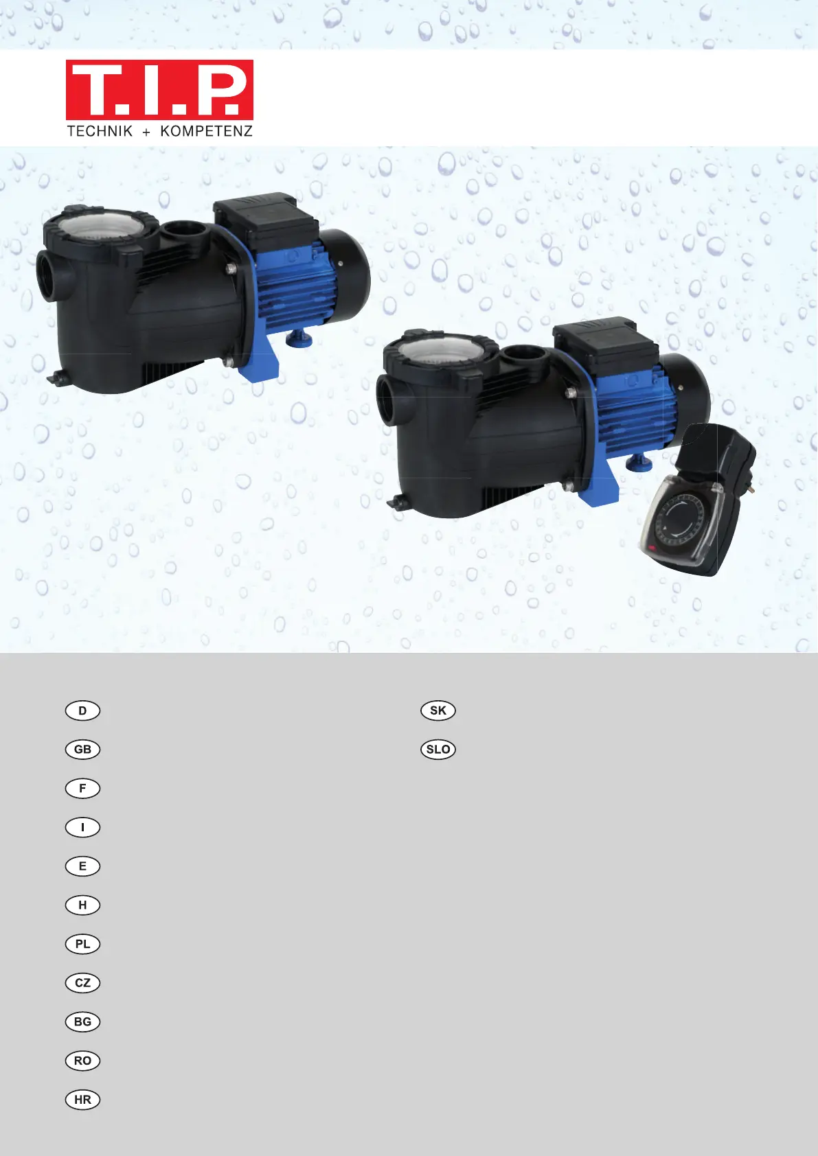
PoolpumpeBazénové čerpadlo
Pool pumpČrpalka za bazene
Pompe pour réservoir
Pompa per piscine
Bomba para piscinas
Medenceszűrő szivattyú
Pompa basenowa
Čerpadlo Pool
Помпа за басейнс
Pompa Pool
Pumpa za bazene
SPP 300 F / SPP 400 FT / SPP 600 FT
SPP 300 F
SPP 400 FT / SPP 600 FT
Produktspecifikationer
| Varumärke: | T.I.P. |
| Kategori: | Vattenpump |
| Modell: | SPP 400 FT |
Behöver du hjälp?
Om du behöver hjälp med T.I.P. SPP 400 FT ställ en fråga nedan och andra användare kommer att svara dig
Vattenpump T.I.P. Manualer

18 Mars 2026
13 September 2025
11 September 2025
11 September 2025
11 September 2025
11 September 2025
11 September 2025
11 September 2025
26 September 2024
19 September 2024
Vattenpump Manualer
Nyaste Vattenpump Manualer
25 Mars 2026
17 Mars 2026
14 Mars 2026
14 Mars 2026
14 Mars 2026
13 Mars 2026
13 Mars 2026
13 Mars 2026
12 Mars 2026
9 Mars 2026