Uni-T UT202A Bruksanvisning
Uni-T Mätutrustning UT202A
Läs gratis den bruksanvisning för Uni-T UT202A (2 sidor) i kategorin Mätutrustning. Guiden har ansetts hjälpsam av 40 personer och har ett genomsnittsbetyg på 4.3 stjärnor baserat på 5 recensioner. Har du en fråga om Uni-T UT202A eller vill du ställa frågor till andra användare av produkten? Ställ en fråga
Sida 1/2
Overview
This Operating Manual covers information on
safety andcautions. Please readtherelevant
informationcarefully andobserveallthe
Warnings and Notes strictly.
Warning
To avoid electric shock or personal injury, read
the “Safety Information” carefully before using
the Meter.
Model UT202A is 2000-count stable, safe and
reliable digital clamp multimeter(hereafter
referred to as "the Meter"). It is designed with
large-scale integrated circuits and A/D
converter as the core as well as the overload
protection and novel structure, which make
it a superb tool for electricians.
The Meter can measure AC/DC Voltage, AC
Current, Resistance, Diodes, and Continuity.
Unpacking Inspection
Open the package case and take out the Meter.
Check thefollowingitems carefully forany
missing or damaged part:
Item Description Qty
1 English Operating Manual 1 piece
2 Test Lead 1 pair
Intheeventyoufindany missingor damaged
part please contact your dealer immediately.
Safety Information
This Metercomplieswiththestandard
IEC61010: PollutionDegree2, Overvoltage
Category (CATII 600V, CAT III 300V) and Double
Insulation.
CATII: Local level, appliance, PORTABLE
EQUIPMENT etc., with smaller transient
overvoltages than CATIII.
CAT III: Distribution level, fixed installation, with
smaller transient overvoltages than CAT IV
Use the Meter only as specified in this operating
manual, otherwisetheprotectionprovidedby
the Meter may be impaired.
In this manual, a Warning identifies conditions
andactionsthat posehazardsto theuser, or
may damage the Meter or the equipment under
test.
A Note identifies the information that user
should pay attention to.
Warning
To avoid possible electric shock or personal
injury, andto avoidpossibledamageto the
Meter or to the equipment under test, adhere to
the following rules:
.esac eht tcepsni reteM eht gnisu erofeB ●
Donot usetheMeterif it is damagedorthe
case (or part of the case) is removed.Look for
cracks or missing plastic.Pay attention to the
insulation around the connectors.
●Inspect the test leads for damaged
insulationorexposedmetal.Checkthetest
leads forcontinuity.Replace damagedtest
leadswithidenticalmodelnumberor electrical
specifications before using the Meter.
●Do not apply more than the rated voltage,
as marked on the Meter, between the terminals
orbetweenanyterminalandgrounding. If the
valueto bemeasuredis unknown, use the
●When measurement has been completed,
disconnecttheconnectionbetweenthetest
leads andthecircuitunder test,removethe
testing leads away from the input terminals of
the Meter and turn the Meter power off.
●The rotary switch should be placed in
the right position and no any changeover of
rangeshallbemadewhenmeasurement is
conducted to prevent damage of the Meter.
●Donot carry out the measurement when
the Meter’s back case and battery compartment
are not closed to avoid electric shock.
●Do not input higher than 600V between the
Meter’s terminals andthegroundingto avoid
electric shock and damages to the Meter.
● When the Meter is working at an effective
voltage over 60V in DC or 30V rms in AC,
special care should be taken for there is danger
of electric shock.
●Use the proper terminals, function, and
range for your measurements.
●Donot use or store the Meter in an
environment of hightemperature, humidity,
explosives, inflammablesandstrongmagnetic
field. The performance of the Meter may
deteriorate after dampened.
●When using the test leads, keep your
fingers behind the finger guards.
●Disconnectcircuit power and discharge
allhigh-voltagecapacitorsbeforetesting
resistance, continuity and diode.
●Replace the battery as soon as the battery
indicatorappears.With a low battery, the
Metermightproduce falsereadingsthatcan
lead to electric shock and personal injury.
●When servicing the Meter, use only use
the replacement parts with the same model
or identical electrical specifications.
● The internal circuit of the Meter shall not be
altered at will to avoid damage of the
Meter and
any accident.
●Soft cloth and mild detergent should be
usedtocleanthesurface oftheMeter when
servicing. Noabrasive andsolvent shouldbe
used to prevent the surface of the Meter from
corrosion, damage and accident.
● The Meter is suitable for indoor use.
● Turn the Meter off when it is not in use and
take out the battery when not using for a long time.
●Constantly check the battery as it may leak
whenit has beenusingforsometime, replace
the battery as soon as leaking appears. A
leaking battery will damage the Meter.
International Electrical Symbols
AC (Alternating Current)
DC (Direct Current)
AC or DC
Grounding
Double Insulated
Warning. Refer to the Operating Manual
Low Battery Indication
Continuity Test
Diode
Conforms to Standards of European Union
The Meter Structure (See Figure 1)
Figure 1
1. Input Terminals
2. LCD Display
3. Functional Buttons
4. Rotary Switch
5. Trigger: press the lever to open the
transformer jaws. When the pressure on the
lever is released, the jaws will close.
6. Hand Guards: to protect user’s hand from
touching the dangerous area.
7. Transformer Jaws: designed to pick up the
AC current flowing through the conductor.
It could transfer current to voltage. The
tested conductor must vertically go through
the jaw center.
maximum measurement position and reduce the
range step by step until a satisfactory reading is
obtained.
Functional Buttons and Auto Power Off
1. HOLD
Press HOLD to enter and exit hold mode. Press
andholdHOLDbuttonwhileturningonthe
Meter, auto power off will be canceled.
2. MAX
Press MAX to start recording and updating of
maximum values.
3. SELECT
Under Ω ranging, resistance
measurement modeis default,press SELECT
to select continuity measurement mode or diode
measurement mode.
4. Auto Power Off
To preserve battery life, the Meter automatically
goes into a “sleep”mode if youdonot pressany
button for around 10 minutes. The Meter can be
activated by pressing any effective button (refer
to The Effectiveness of Functional Buttons),
thenreturntothedisplayforthefunction
selected previously.
5. Buzzer
Thebuzzersounds every time a effective button
is pressed down.When the meter will auto
poweroff in1 minute thebuzzerbeepsfive
times. Before power off there will be a long time
buzzer beeps.
6. The Effectiveness of Functional Buttons
Not every functionalbuttons canbeusedon
every rotary switch positions.Below table
describewhichfunctionalbuttonscanbeused
on which rotary switch positions
Rotary Functional Buttons
Switch SELECT MAX HOLD
Positions
Ω • N/A •
N/A • •
N/A • •
A 20A N/A • •
A 200A N/A • •
A 600A N/A • •
Display Symbols (See Figure 2)
Number
Description
1 Indicator for AC voltage or current
2 Indicator for DC voltage
3 The battery is low.
Warning: To avoid false readings, which
could lead to possible electric shock or
personal injury, replace the battery as soon as
the battery indicator appears.
4 The Meter is in the auto range mode in
which the Meter automatically selects
the range with the best resolution.
5 Test of diode
6 The continuity buzzer is on
7 Maximum reading displayed
8 Data hold is active
9 Amperes (amps). The unit of current.
10 Ω: Ohm. The unit of resistance.
kΩ:Kilohm. 1000 ohms
MΩ:Megohm. 1,000,000 ohms
11 V: Volts. The unit of voltage.
mV: Millivolt. 0.001 volts
12 Indicates negative reading
Figure 2
Measurement Operation
A. Measuring DC Voltage (See Figure 3)
Warning
To avoid harm to you or damage to the Meter
fromeletricshock, donotattempttomeasure
voltages higher than 600V AC/DC.
To measure DC voltage, connect the Meter as
follows:
1. Insert the red test lead into the
terminal and the black test lead into the
COM terminal.
2. Set the rotary switch to .
3. Connect the test leads across with the object
being measured.
VΩ
The measured value shows on the display.
Figure 3
Note:
When DC voltage measurement has been
completed, disconnect theconnectionbetween
thetestingleadsandthecircuitunder test and
remove testing leads from the input terminals.
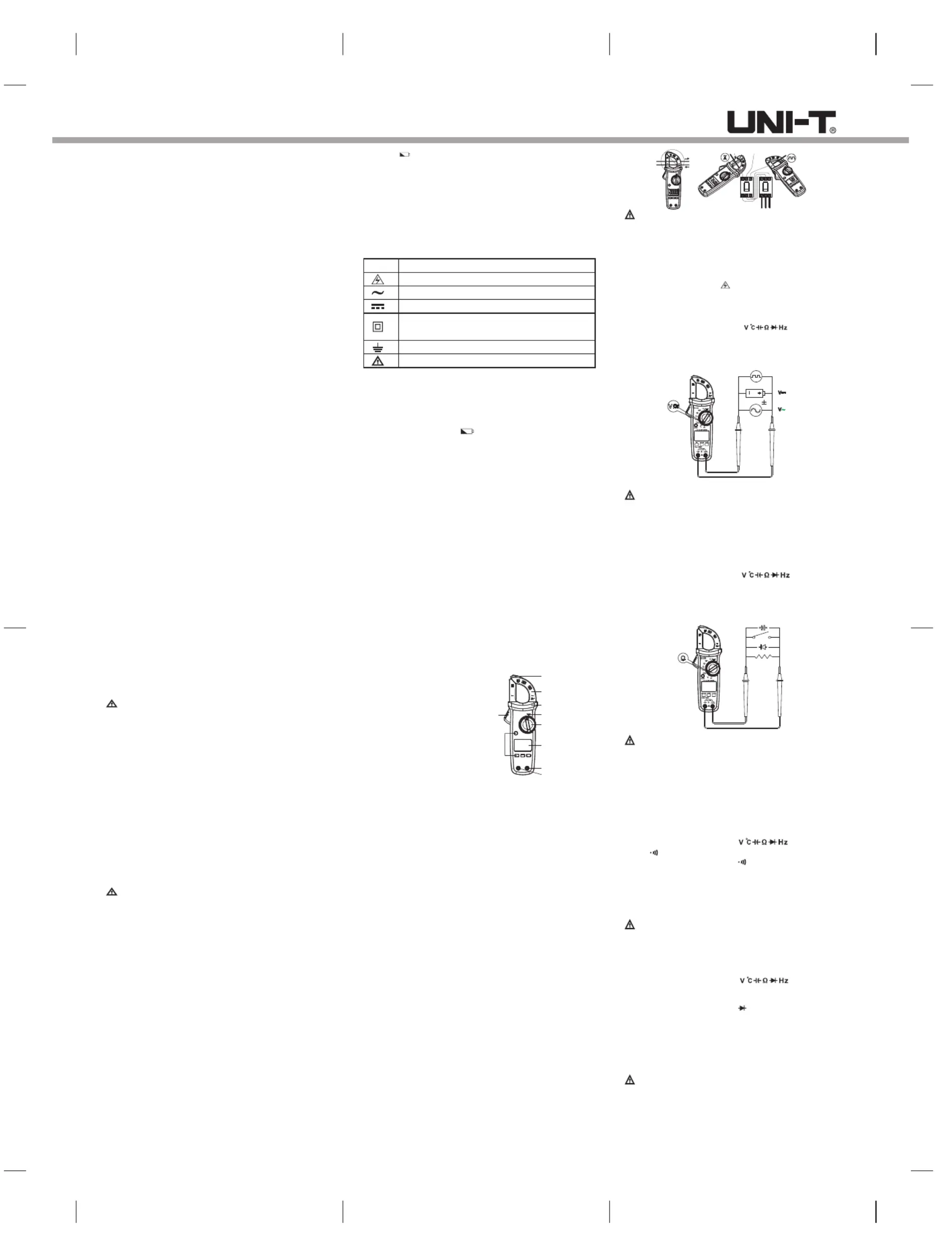
B. Measuring AC Voltage (See Figure 4)
Warning
To avoid harm to you or damage to the Meter
fromeletricshock, donotattempttomeasure
voltages higher than 600V AC/DC.
To measure AC voltage, connect the Meter as
follows:
1. Insert the red test lead into the
terminal and the black test lead into the
COM terminal.
2. Set the rotary switch to .
3. Connect the test leads across with the object
being measured.
The measured value shows on the display.
VΩ
Figure 4
Note:
WhenACvoltagemeasurementhasbeen
completed, disconnect theconnectionbetween
thetestingleadsandthecircuitunder test and
remove testing leads from the input terminals.
C. Measuring Resistance (See Figure 5)
Warning
To avoid damage to the Meter or to the
devices under test, disconnect circuit power and
discharge all the high-voltage capacitors before
measuring resistance.
To measure resistance, connect the Meter as
follows:
1. Insert the red test lead into the
terminal and the black test lead into the
COM terminal.
2. Set the rotary switch to ; resistance
measurement (Ω) is default or press
SELECT button to select Ω measurement
mode
3. Connect the test leads across with the object
being measured.
The measured value shows on the display.
Note:
●Separating the objects being tested from
the circuit when measuring can obtain a more
accurate result.
Ω
VΩ
Figure 5
●Whenresistance measurement has been
completed, disconnect theconnectionbetween
thetestingleadsandthecircuitunder test and
remove testing leads from the input terminals.
Produktspecifikationer
| Varumärke: | Uni-T |
| Kategori: | Mätutrustning |
| Modell: | UT202A |
| Vikt: | 220 g |
| Bredd: | 75.6 mm |
| Djup: | 30 mm |
| Höjd: | 210 mm |
| Certifiering: | CE, RoHS |
| Produktens färg: | Black, Red |
| bruksanvisning: | Ja |
| väska: | Ja |
| Batterispänning: | 9 V |
| Batterier medföljer: | Ja |
| Displaytyp: | Analog |
| Mätningskategori: | CAT II 600V, CAT III 300V |
| Testkablar: | Ja |
| Växelströmsspänning: | 600 V |
| Likströmsspänning: | 600 V |
| Resistans (max): | 0.02 Ω |
Behöver du hjälp?
Om du behöver hjälp med Uni-T UT202A ställ en fråga nedan och andra användare kommer att svara dig
Mätutrustning Uni-T Manualer

3 April 2025
3 April 2025
3 April 2025
3 April 2025
3 April 2025
3 April 2025
3 April 2025
3 April 2025
3 April 2025
3 April 2025
Mätutrustning Manualer
Nyaste Mätutrustning Manualer
1 April 2025
1 April 2025
1 April 2025
1 April 2025
1 April 2025
1 April 2025
1 April 2025
1 April 2025
1 April 2025
1 April 2025