Uni-T UT512 Bruksanvisning
Uni-T Mätutrustning UT512
Läs gratis den bruksanvisning för Uni-T UT512 (2 sidor) i kategorin Mätutrustning. Guiden har ansetts hjälpsam av 24 personer och har ett genomsnittsbetyg på 4.4 stjärnor baserat på 2 recensioner. Har du en fråga om Uni-T UT512 eller vill du ställa frågor till andra användare av produkten? Ställ en fråga
Sida 1/2
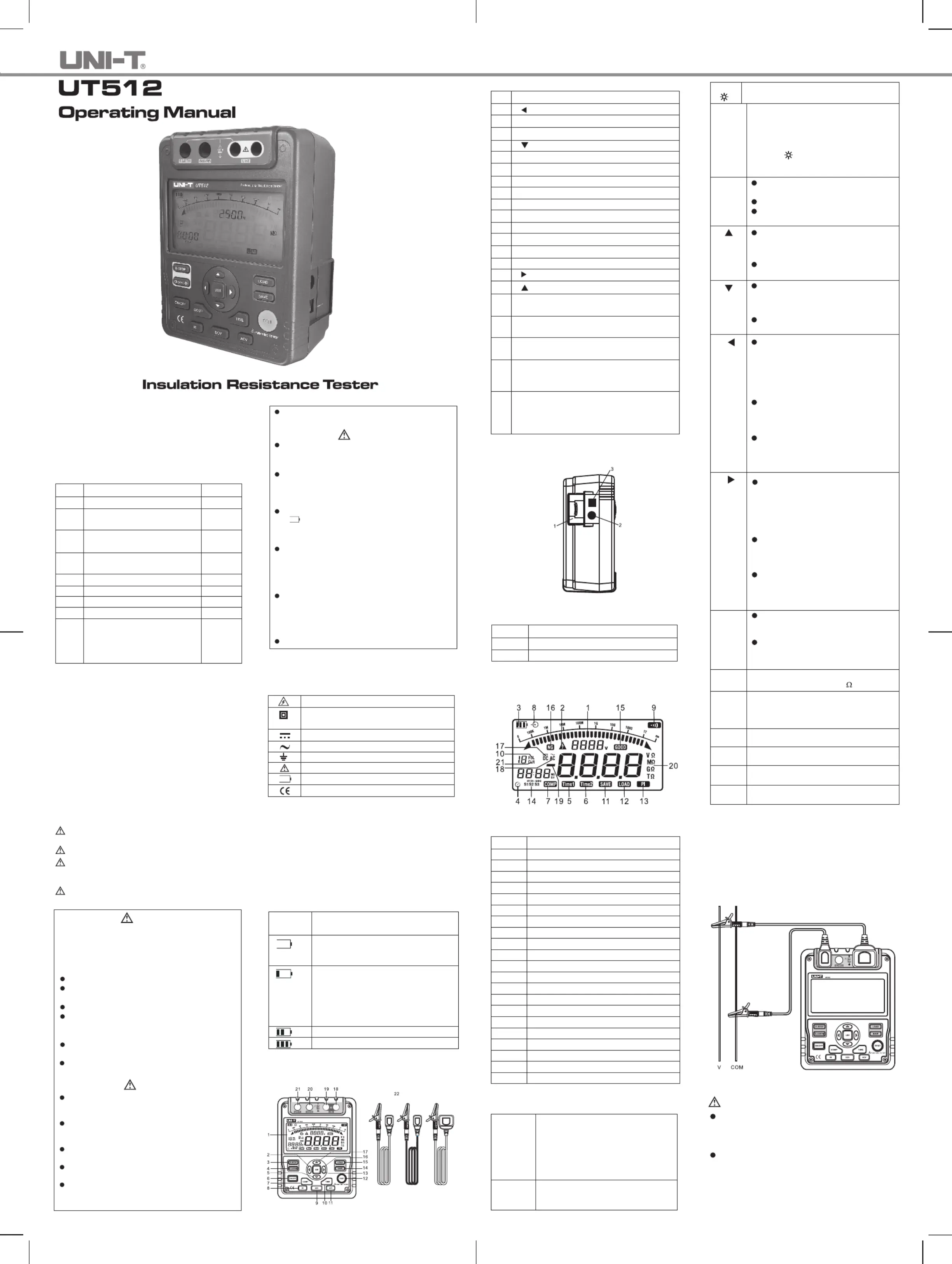
Introduction
Uni-rendModelUT512insulationresistancetesteT r
(hereafte"theMeter")ishandheldinstrumenr, a t
designedprimarilymakeresisanceinsulaio to t/ tn
resistance measurement.
Unpacking the Meter
The Meter includes the following items:
Table 1. Unpacking Inspection
Item
1
2
3
4
5
6
7
8
9
Description
English Operating Manual
One-plug tt eslead to one alligator
clip ( Black )
O nepluges tt lead to one alligator
clip ( Green )
Two-plug test lead to one
alligator clip ( Red )
1.5V Battery (LR14 / R14)
Tool Box
USB Interface Cable
Software
Power adaptor (input voltage
230V, 50/60Hz, 50mA, output
DC14.5V, 600mA) (optional,
available at extra cost)
Qty
1 pc
1 pc
1 pc
1 pc
8 pcs
1 pc
1 pc
1 pc
1 pc
Intheeventyoufindanymissingordamage,pleas e
contact your dealer immediately.
Safety Information
T hisMeercompliest with EN 61010-1:2010 fety sameasurement
requirement:Pollution Degree 2, measurement
category CAT III 600V and Double Insulation.
CAT II (measurement category): Test and measuring
circuits connected directly to utilization points (socket outlets
and similar points) of the low-voltage MAINS installation.
Use the Meter only as specified in this operating manual,
otherwisetheprotectionprovided bytheMetermay be
impaired.
Danger identifies conditionsandactions thatpos e
hazard(s) to the user.
Warning alerts users to avoid electric shock.
Cautionidentifies conditionsandactions thatma y
damage the Meter and affect accurate
measurement.
Danger
Useof instrumentin a manualnot specifed byth e
manufactuer may impair safety features/protection
proved by the ent.d the fgidquipme Reaollowin
sarmacarerefety infotion fullfoy be us oring
servicing the instrument.
Do not apply more than 600V.
Do not use the Meter around explosive gas,
vapor or dust.
Do not use the Meter in a wet environment.
Whenusingthetest leads,keepyourfigure s
away from the lead contacts. Keep your
figuresbehind the fingerguards ontheleads .
Do t u the th any p or cornoseMeterwiartsve
removed.
Operating Caution identifies conditions that user
needs to t akeexrat careduringopera ting the Meter
Warning
Donotuse theMeter ifitis damagedor metal
part is exposed. Look for cracks or missing
plastic.
Be careful when working above33V rms,46.7 V
ac rms or70V DC.Suchvoltages pose a shock
hazard.
Dischargeall loadingof circuit under testafte r
measuring high voltage.
When carrying out insulation measurement,
do not contact the circuit under test.
Caution
Whenperforming resistancetests,remove all
power from the circuit to be measured and
discharge all the power.
Whingthen icserv e Meter, u y seonlonly the
test leads and power adaptor with the same
model number or identical electrical
specifications.
Do not use the Meter if the battery indicator
(
) a showsbatteryemptycondition. Take
thebatteryoutfrom theMeterifit isnotuse d
for a long time.
Do not use or store the Meter in an
environment of high temperature, humidity,
explosive, inflammable and strong magnetic
field. The performance of the Meter may
deteriorate after dampened.
So cth a m dftlondildetergent s be udhouldse
to clean the surface of the Meter when
servicing.Noabrasiveand solventshould be
ud to pnt the su of the omsereverfaceMeterfr
corrosion, damage and accident.
Dry the Meter before storing if it is wet.
Risk of electric shock
Grounding
Empty of Built-In Battery
Conormsf to St of andardsEuropeanUnion
International Electrical Symbols
International symbols on the Meter and in this manual
are explained in Table 2.
Table 2. International Electrical Symbols
Battery Saver (Sleep Mode)
TheMeter enterstheSleep Mode andblanks thedispla y
ifthereisnobuttonpressfor15minutes.Thisisdon e
toconservebatterypoweTheMetercomesout r. of
SleepModewhebuttonispressedandhol n ON/OFF d
for 1 second.
Battery Indication
There is a battery indicator shown on the upper left corner
of the display. Please refer to Table 3 for detailed
explanation.
Battery Voltage
5.9V ~ 10.6V. It means the battery is
empty, Do not use the Meter as it
cannot
guarantee accuracy.
10.7V ~ 11.1V. It means the battery is
almost empty, replacing battery is
necessary. Atthis status,the Meter can
still output 500V and 1000V to measure,
the measured accuracy will not be
affected.
11.2V ~ 12.2V
12.2V or more
Table 3. Battery Indication
Battery
Indicator
The Meter Structure
BelowFigureand 1 TableshowstheMeterfron 4 t
structure and description
Do not change battery when the Meter is in
wet environment.
Place test leads in proper input terminals.
Make sure all the test leads are firmly
connected to the Meter's input terminals.
Make sure the Meter is turned off when
opening the battery compartment.
Figure1.TheMeterFrontStructur e
GnkreeBlac
Red
1
2
3
4
5
6
7
8
9
10
11
12
13
14
15
16
Table 4. Meter Front Description
LCD
Arrow Button
Emergency Stop
Data Clear the Display Backlight Button
Arrow Button
On/Off Button
Compare Button
Insulation Resistance Button
DC ButtonVoltage Measurement
Timer Button.
AC ButtonVoltage Measurement
Test Button
USB Button
Data Store Button.
Data Recall Button
Arrow Button
17
18
19
20
21
22
Arrow Button
LINE: High voltage input terminal
( Connected to two-plug red test lead )
High voltage line shielding input terminal
( Connected to two-plug red test lead )
GUARD: Grounding protection input terminal
( Connected to one-plug black test lead )
EATH:R Highresistance measurement input
terminal ( Connected to one-plug green
test lead )
Testing leads:
Two-plug te redstleadonealliga to torlip c.
One-plug k tblacesleadt to onealligaort clip.
One-plug green test lead to one alligator clip.
Below Figure 2 and Table 5 shows the Meter side
structure and description
Figure 2. The Meter Side Structure
TableideDeipio 5. Meter S scrtn
1 Safety Shutter
2 Power adaptor Input Terminal
3 USB Port
Display
Table 6 and Figure 3 describe the display.
Figure 3. Display
Table 6. Display Description
Number
1
2
3
4
5
6
7
8
9
10
11
Meaning
Analogue bar graph
Risk of electric shock
Battery life indicator
Indicator for timer
Timer 1 symbol
Timer 2 symbo
Indicatesselectedpass/failcompare value
Indicator for power adaptor
The continuity buzzer is on
Indicator for data store full
Data store is on
12
13
14
15
16
17
18
19
20
21
Data recall is on
Indicator for polarization index
Step symbol
Compare result: Pass
Compare result: Fail
Indicator for DC voltage
Indicator for AC voltage
Indicates negative reading
Unit symbols
Indicator for clearing
Table 7. Key Description
Turn on or off the Meter. Press and
holdhe t buonortt f 1 to t thesecondurn
Meter on. Press again to turn off the
Meter.
The Meter defaults at 500V range and
under continuous measurement of
insulation resistance when turned on.
Emergency stop button. Press this
button when the Meter crashes down
and cannot turn off the power.
Key Functions
ON/OFF
E-STOP
Short press to turn on or off the display
backlight
Long press to clear thestored data.
Press to store the current measurement
value. Themaximum numberof stored
reading is 18.Whenthe stored readings
memory is full, the Meter shows FULL
and stop storing. Press and hold
CLEAR /
to clear the stored value
inorder to st t t torehenexmeasuremen
CLEAR
/
SAVE
value.
LOAD
Press once to recall the first stored
value.
Press again to exit Load feature.
Load feature can only be used when
there is no high voltage output.
When the insulation resistance
measurement has no testing voltage
output, press to select previous voltage
range.
Under load mode: press to recall the
previous stored value.
When the insulation resistance
measurement has no testing voltage
output, press to select next voltage
range.
Under load mode: press to recall the
next stored value.
When setting the timer for the
measurement of insulationresistanc e
or polarization index, press to
decrementthetime. Themaximu m
length of time is 15 minutes and 30
seconds, theMeter willautomaticall y
carry out measurement.
When compare function is enabled for
insulation resistance measurement,
press to decrement a resistance
comparing value.
After polarization index measurement,
press to display polarizationindex,
TIME 2 and TIME 1 insulation
resistance values in sequence.
When setting the timer for the
measurement of insulationresistanc e
or polarization index, press to
increment the time. The maximum
length of time is 30 minutes and 30
sec tonds,he Meter will automaticyall
carry out measurement.
When compare function is enabled for
insulation resistance measurement,
press to increment a resistance
comparing value.
After polarization index measurement,
press to display t polarizaionindex,
TIME2 and TIME 1 insulation
resistance values in sequence.
Press once to start the data
transferring to the computer viaUSB ,
USBsymbol shows on the display.
Press again to stop the data
transferring to the computer viaUSB ,
USBsymbol disappears.
USB
Set a pass / faillimit for insulation tests.
The default value is 10M
Press to step through continuous,
timed and polarization index
measurements in sequence.
Press to turn on/off the output of
insulation resistance test voltage.
Press to initiate insulation resistance
measurement
Press to initiate DC voltage
measurement
Pres to initiate AC voltage
measurement
COMP
TIME
TEST
IR
DCV
ACV
Measurement Operation
This section explains how to make measurements.
Press and hold to turn on the Meter, pressON/OFF
againtoturn off theMete r. The meter defaults at 500V
range and continuous measurement of insulation
resistance when turned on.
A. Measuring Voltage
Figure 4. Voltage Measurement
Red
Green
To avoid harm to you ordamage tothe Meter,
please do not attempt to measure voltages
higher than 600V or 600V rms, although
readings may be obtained.
Specialcareshouldbetaken whenmeasurin g
high voltage.
Operating Caution
To msure vt, set t Meter as Fre 4 eaolageupheiguand
do the following:
Press or button to select DC voltage orDCVACV
AC voltage measurement
1.
CAT III (measurement category): Test and measuring
circuits connected to the distribution part of the building’s
low-voltage MAINS installation.
Equipment protected throughout by DOUBLE
INSULATION or REINFORECD INSULATION
Direct current
Alternating current
Caution
Produktspecifikationer
| Varumärke: | Uni-T |
| Kategori: | Mätutrustning |
| Modell: | UT512 |
Behöver du hjälp?
Om du behöver hjälp med Uni-T UT512 ställ en fråga nedan och andra användare kommer att svara dig
Mätutrustning Uni-T Manualer

3 April 2025
3 April 2025
3 April 2025
3 April 2025
3 April 2025
3 April 2025
3 April 2025
3 April 2025
3 April 2025
3 April 2025
Mätutrustning Manualer
Nyaste Mätutrustning Manualer
1 April 2025
1 April 2025
1 April 2025
1 April 2025
1 April 2025
1 April 2025
1 April 2025
1 April 2025
1 April 2025
1 April 2025