Vimar 01420.B Bruksanvisning
Vimar Inte kategoriserad 01420.B
Läs gratis den bruksanvisning för Vimar 01420.B (76 sidor) i kategorin Inte kategoriserad. Guiden har ansetts hjälpsam av 14 personer och har ett genomsnittsbetyg på 4.5 stjärnor baserat på 9 recensioner. Har du en fråga om Vimar 01420.B eller vill du ställa frågor till andra användare av produkten? Ställ en fråga
Sida 1/76
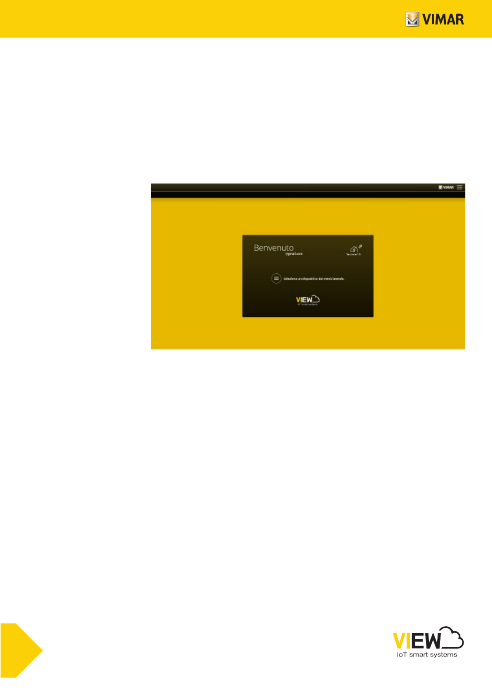
Installer manual
VIEW IoT Smart Systems
Integrated interconnected systems platform.
Installer Mario 1960
Produktspecifikationer
| Varumärke: | Vimar |
| Kategori: | Inte kategoriserad |
| Modell: | 01420.B |
Behöver du hjälp?
Om du behöver hjälp med Vimar 01420.B ställ en fråga nedan och andra användare kommer att svara dig
Inte kategoriserad Vimar Manualer

7 April 2025
3 April 2025
3 April 2025
3 April 2025
3 April 2025
2 April 2025
2 April 2025
2 April 2025
2 April 2025
2 April 2025
Inte kategoriserad Manualer
Nyaste Inte kategoriserad Manualer
9 April 2025
9 April 2025
9 April 2025
9 April 2025
9 April 2025
9 April 2025
9 April 2025
9 April 2025
9 April 2025
9 April 2025