Advantech IDAQ-873-A Bruksanvisning
Advantech Inte kategoriserad IDAQ-873-A
Läs gratis den bruksanvisning för Advantech IDAQ-873-A (54 sidor) i kategorin Inte kategoriserad. Guiden har ansetts hjälpsam av 20 personer och har ett genomsnittsbetyg på 4.2 stjärnor baserat på 3 recensioner. Har du en fråga om Advantech IDAQ-873-A eller vill du ställa frågor till andra användare av produkten? Ställ en fråga
Sida 1/54
User Manual
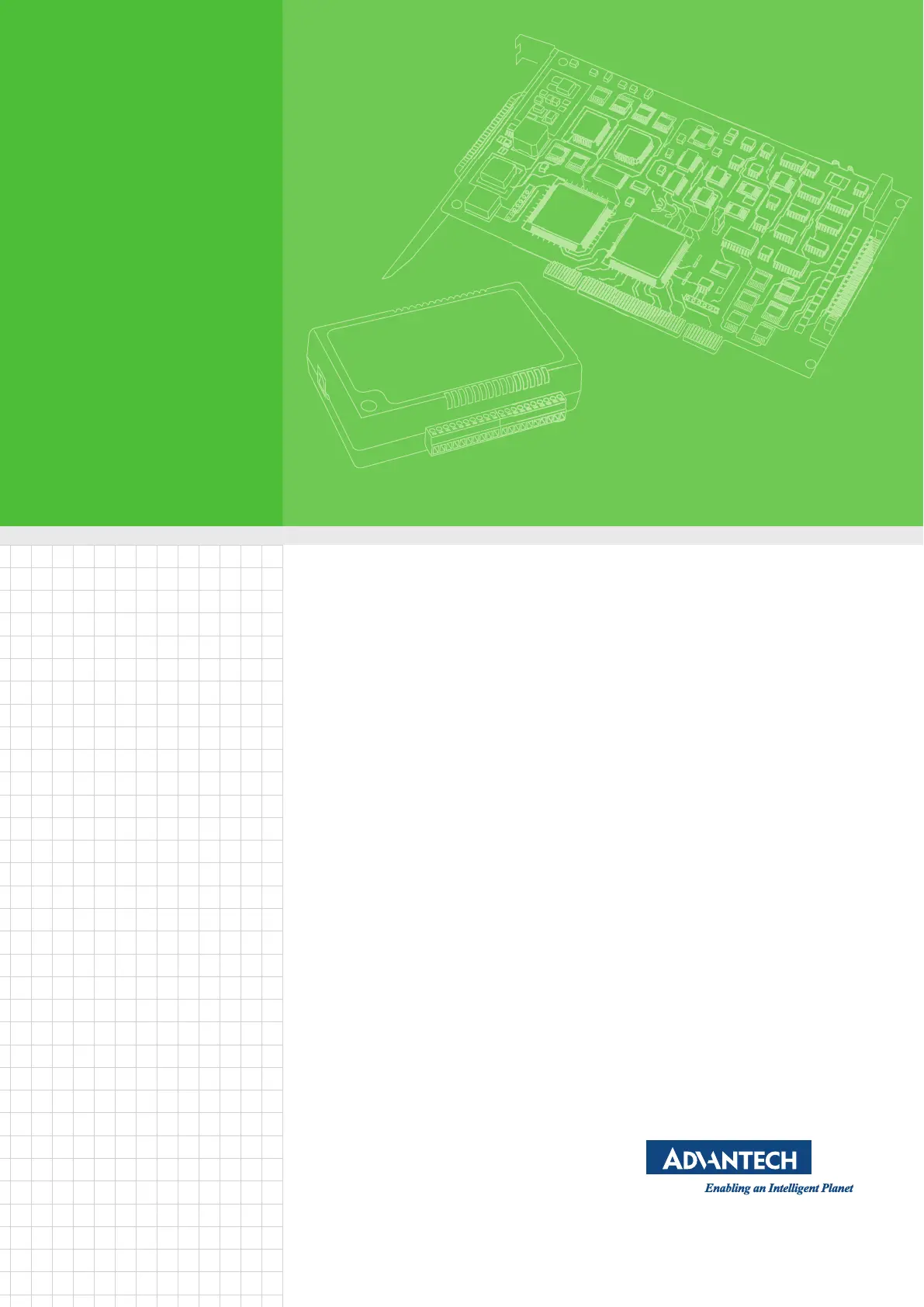
iDAQ-871/873
Bridge Input Industrial DAQ
Modules
Produktspecifikationer
| Varumärke: | Advantech |
| Kategori: | Inte kategoriserad |
| Modell: | IDAQ-873-A |
Behöver du hjälp?
Om du behöver hjälp med Advantech IDAQ-873-A ställ en fråga nedan och andra användare kommer att svara dig
Inte kategoriserad Advantech Manualer

11 Februari 2025
11 Februari 2025
10 Februari 2025
8 Februari 2025
8 Februari 2025
8 Februari 2025
8 Februari 2025
8 Februari 2025
8 Januari 2025
3 Januari 2025
Inte kategoriserad Manualer
Nyaste Inte kategoriserad Manualer
9 April 2025
9 April 2025
9 April 2025
9 April 2025
9 April 2025
9 April 2025
9 April 2025
9 April 2025
9 April 2025
9 April 2025