AFX Lake LAKS0513LAJUDBK Bruksanvisning
Läs gratis den bruksanvisning för AFX Lake LAKS0513LAJUDBK (2 sidor) i kategorin Lättnad. Guiden har ansetts hjälpsam av 18 personer och har ett genomsnittsbetyg på 4.5 stjärnor baserat på 6 recensioner. Har du en fråga om AFX Lake LAKS0513LAJUDBK eller vill du ställa frågor till andra användare av produkten? Ställ en fråga
Sida 1/2
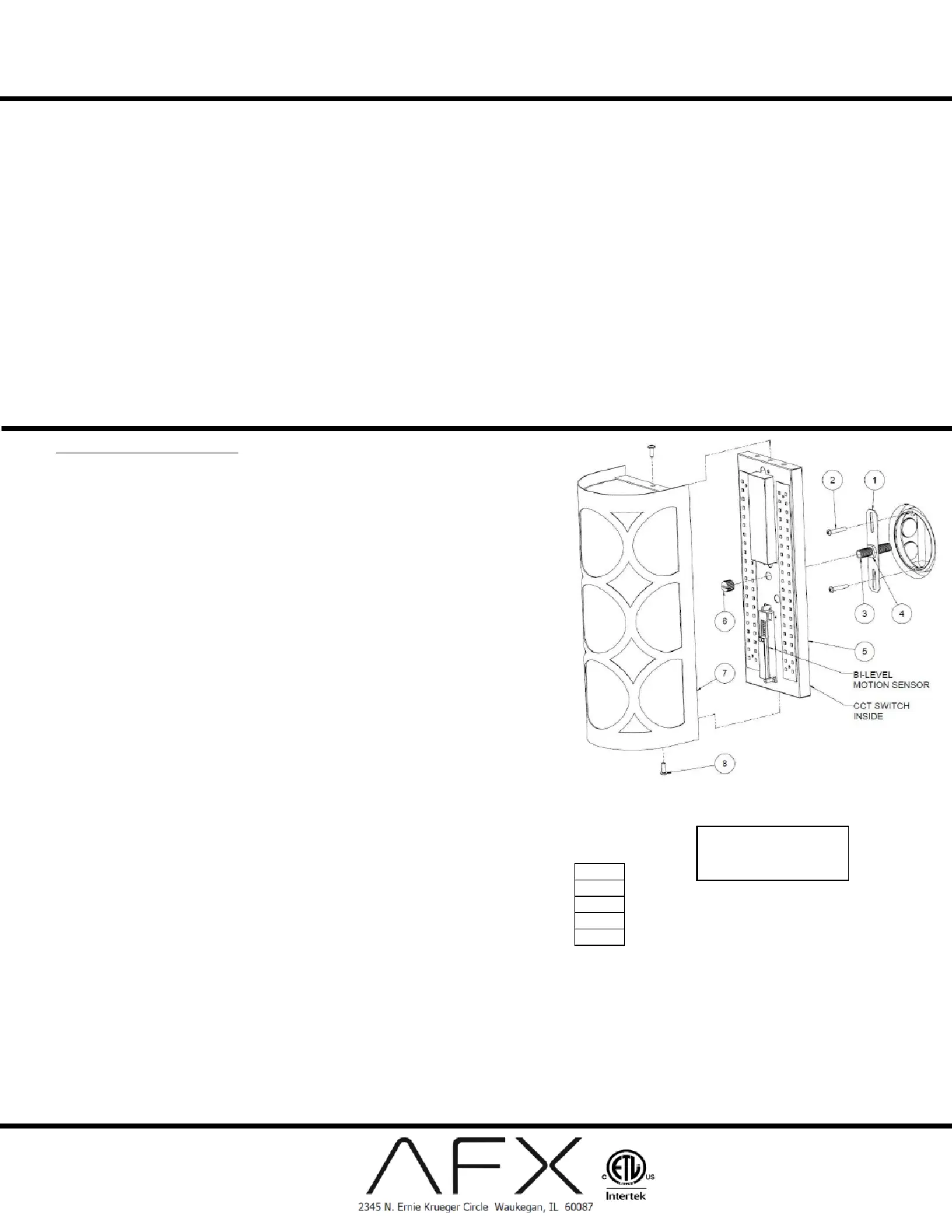
LED door Luminaires In
Surface Mount–Bi-level MS
12027-7VAC 60Hz/
Page of 6 R01 2 806194
Model #: APS, EVNS, HVNS,
LBTS, LAKS,
View shown for reference
only. Individual models
may vary.
Safety Precautions
•Read all safety precautions and installation instructions carefully before installing or servicing this xture. Failure to comply with these instructions could result in potentially fatal electric shock and/or
property damage.
•is recommended that a qualied electrician perform all the wiring. This xture must be wired in accordance with all national and local electrical codes. It
•Do not handle any energized xture or attempt to energize any xture with wet hands or while standing on a wet or damp surface or in water.
•This xture is designed for use in a 120-VAC / 60Hz circuit. This xture is compatible with a TRIAC (forward-phase or leading-edge) / ELV (reverse-phase or trailing-edge) and 0-10V dimming 277
circuit.
•Make sure that the power source conforms to the requirements of the xture. (See labels on the xture housing).
•To reduce the risk of electrical shock, and to assure proper operation, this xture must be adequately grounded. To accomplish proper grounding, there must be a srate ground wire (green) epa
contact between this xture and the ground connection of your main power supply panel.
•This xture is intended to be used for general indoor lighting in dry or damp locations.
•Disclaimer
Changes or modications not expressly approved by the party responsible for compliance could void the user’s authority to operate the equipment. NOTE: This equipment has been tested and
found to comply with the limits for a Class B digital device, pursuant to Part 15 of the FCC Rules and Canan ICES-005 (B) / NMB-005 (B). These limits are designed to provide reasonable adi
protection against harmful interference in a residential installation. This equipment generates, uses, and can radiate radio frequency energy and, if not installed and used in accordance with the
instructions, may cause harmful interference to radio communications. However, there is no guarantee that interference will not occur in a particular installation. If this equipment does cause harmful
interference to radio or television reception, which can be determined by turning the equipment o and on, the user is encouraged to try to correct the interference by one or more of the following
measures:
• Reorient or relocate the receiver antenna.
• Increase the separation between the equipment and receiver.
• Connect the equipment into an outlet on a circuit different from that to which the receiver is connected.
• Consult with the dealer or an experienced radio/TV technician for help.
Any modications to this xture may void the warranty and interfere with the safe operation of the luminaire.
Operation is subject to the following two conditions: (1) this device may not cause interference, and (2) this device must accept any interference, including interference that may cause undesired
operation of the device.
Assembly Instructions
Step 1 Preparing for installation–
A. at the fuse or circuit breaker box before installing or servicing any part of this Disconnect electrical power
xture.
B. Carefully remove the xture and hardware kit from the carton.
C. Remove components from the hardware kit.
D. Install 1/8- protrude above the 27 threaded stem (3) to mounting bracket (1), allow approximately 0.75” to
bracket then use hex nut (4) to secure it.
E. Install mounting bracket (1) to the 3/0 or 4/0 junction box (not included) using two screws #8- (2) to secure 32
it.
Wiring All wiring must take place inside junction box (not included) –
Caution: Make sure power is o at the fuse or circuit breaker box. Check power es for damage or scrapes. wir
If power supply wires are within three inches of the D driver, use wire suitable for at least 90°C (194°F). LE
Note: Most dwellings built before 1985 have supply wire rated to 60°C. Consult a qualied electrician to
ensure correct branch circuit conductor before installing.
Step 2 Wiring xture –
A. Make all wire connections to approprte wire. Secure with wire nuts (provided).ia
B. Connect the green wire from the xture to the supply power source ground wire.
C. Connect the white wire from the xture to the white (N) wire from the supply power For non-dimming.
source. Connect the black xture wire to the black (L) wire from the supply power sourc Pink and purple e.
wires are not to be used and must be individually capped to prevent shorting.
D. Connect the white wire from the xturto coesponding neutral (N) wire in accordance For TRIAC dimming.e rr
with the dimmer manufacturer instructions. Connect the black wire from the xture to the corresponding
control line (L) wire in accordance with the dimmer manufacturer instructi. Pink and purple wires are not to ons
be used and must be individually capped to prevent shorting.
E. Connect the pink wire from the xture to the dimmer source gray or pink wire. Connect For 0-10V dimming.
the purple wire from the xture to the dimmer source purple wire. Connect the white wire from the xture to the neutral (N)
wire from the dimm supply source per dimmer wiring instructions. Connect the black wire from the xture to the control er
line (L) wire from the dimmer supply power source per dimmer wiring instructions.
F. ll on each wire lead to ke sure connections are secure. Make certain no bare wires are exposed outside of wire Do not mix wires.Puma
connectors. Tuck all connections neatly into the junction box.
Step 3 Color changing temperature adjustment, CCT (if desired) –
A. Adjust CCT switch inside the xture according to the desired color temperature of 2700K, 3000K, 3500K,
4000K, or 5000K as shown below. Note: Fixture is preset to 3000K from factory.
Step 4 Mounting –
A. Instaxture (5to the mounting bracket using barrel nut (6 secure i ll ) ) tot.
Step 5 Diuser –
A. Instaxture (5to the mounting bracket using barrel n ll )
Step 6 Restore power at the fuse or circuit breaker box –
Step 7 -Level Motion Sensor Operation –Bi
A. The factory will set dip switch to 100% detection, seconds Hold Time, Disable Daylight Sensor, 0 seconds Standby Period and 30% dimNote: To select other settings follow dip switch chart 5 .
below.
• 2700K
•3000K
•3500K
•4000K
•5000K
Produktspecifikationer
| Varumärke: | AFX |
| Kategori: | Lättnad |
| Modell: | Lake LAKS0513LAJUDBK |
Behöver du hjälp?
Om du behöver hjälp med AFX Lake LAKS0513LAJUDBK ställ en fråga nedan och andra användare kommer att svara dig
Lättnad AFX Manualer

2 April 2025
13 Oktober 2024
12 Oktober 2024
26 September 2024
26 September 2024
26 September 2024
26 September 2024
26 September 2024
26 September 2024
26 September 2024
Lättnad Manualer
Nyaste Lättnad Manualer
9 April 2025
9 April 2025
9 April 2025
8 April 2025
8 April 2025
8 April 2025
7 April 2025
5 April 2025
5 April 2025
5 April 2025