American Standard Monterrey 6500145.002 Bruksanvisning
American Standard Kran Monterrey 6500145.002
Läs gratis den bruksanvisning för American Standard Monterrey 6500145.002 (2 sidor) i kategorin Kran. Guiden har ansetts hjälpsam av 38 personer och har ett genomsnittsbetyg på 4.3 stjärnor baserat på 7 recensioner. Har du en fråga om American Standard Monterrey 6500145.002 eller vill du ställa frågor till andra användare av produkten? Ställ en fråga
Sida 1/2
SPREAD LAVATORY
FAUCETS
Installation
Instructions
6500
6501
6502
6530
6531
6532
Thank you for selecting American-Standard...
the benchmark of fine quality for over 100 years.
To ensure that your installation proceeds smoothly--
please read these instructions carefully before you begin.
Certified to comply with ANSI A112.18.1M
60186 Rev. 1.3
1
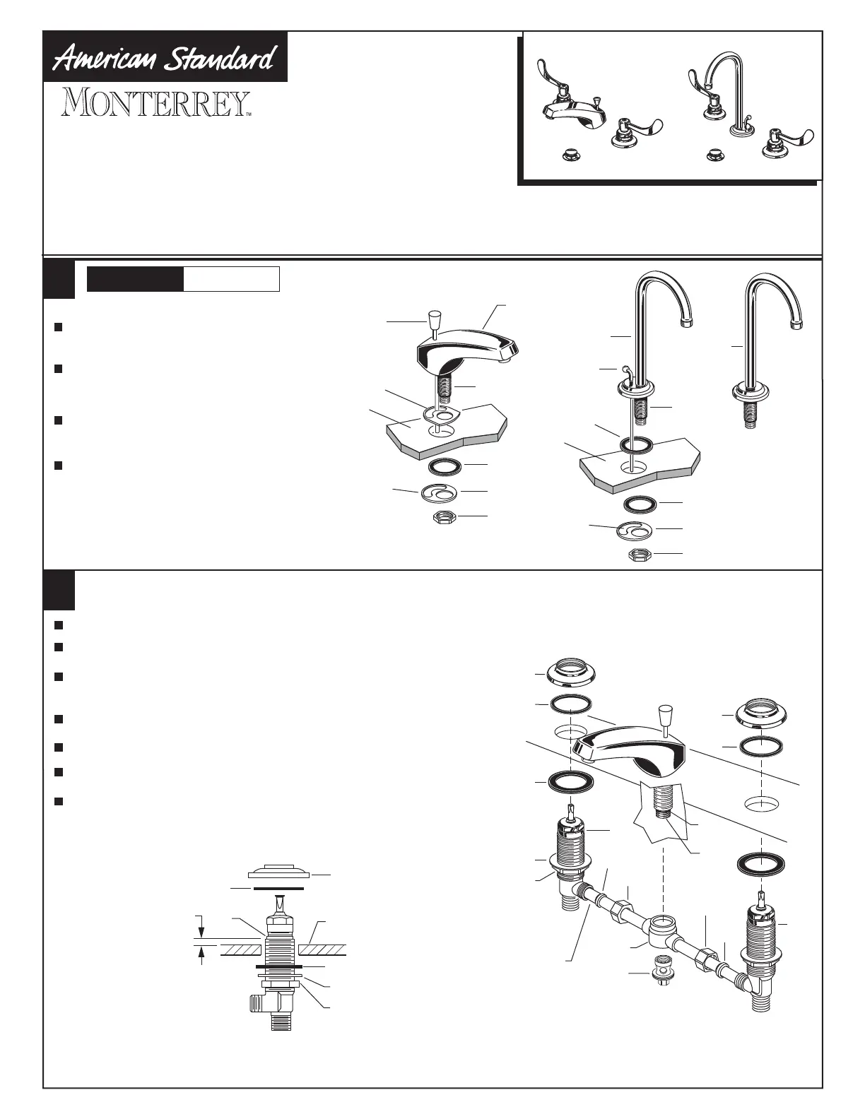
GOOSE NECK
SPOUT (POP-UP)
CONVENTIONAL SPOUT
Insert SPOUT SHANK (1, 1a) through
center hole of SINK, making sure
RUBBER GASKET (2, 2a) is properly positioned.
CONVENTIONAL OR GN SPOUT ASSEMBLY
Assemble RUBBER WASHER (3),
RETAINER (4) and LOCKNUT (5) onto
threads of SPOUT SHANK (1, 1a) from
underside of SINK.
Insert LIFT ROD (6, 6a) through SPOUT
and slot of BRASS WASHER (4).
Align SPOUT and tighten LOCKNUT (5).
Be sure slot in BRASS WASHER (4) is
positioned to the rear as shown.
Turn off water at
main supply.
CAUTION
SINK
SLOT
SINK
SLOT
GOOSE NECK
SPOUT
10
3
5
5/16'' MIN.
MOUNTING SURFACE
11
11
1
2
3
1
2
1
3
4
6
6a
5
3
4
5
2
2a
2
Push TUBING (4) ends into VALVE (5) side outlets. Insert VALVES (5)
into mounting holes from underside of ledge.
Install LOCKNUTS (1), BRASS WASHERS (2) and RUBBER WASHERS (3) onto valve shanks.
Place RUBBER RING (11) into DECK ADAPTERS (10) and thread onto
valves until snug against internal stop.
Tighten LOCKNUT (1) to secure VALVE (5) position.
Slide FERRULE (13) and COUPLING NUT (14) to outlet of VALVE (5) and tighten
COUPLING NUT (14) firmly.
Connect HOT water supply to inlet of left VALVE and COLD water supply to inlet of
right VALVE using appropriate connector.
VALVE ASSEMBLY
HOT
COLD
13
5
14
8
7
9
6
14
13
4
5
10
MOUNTING
LEDGE
11
10
Press TEE (6) onto SPOUT SHANK (7) making certain that the O-RING (8) is
properly seated on SHANK (7). Push COUPLING (9) into TEE (6) and
attach to SPOUT SHANK (7) and tighten.
1a
Produktspecifikationer
| Varumärke: | American Standard |
| Kategori: | Kran |
| Modell: | Monterrey 6500145.002 |
Behöver du hjälp?
Om du behöver hjälp med American Standard Monterrey 6500145.002 ställ en fråga nedan och andra användare kommer att svara dig
Kran American Standard Manualer

8 Oktober 2025
8 Oktober 2025
8 Oktober 2025
8 Oktober 2025
3 Januari 2025
3 Januari 2025
1 September 2024
Kran Manualer
Nyaste Kran Manualer
3 April 2026
3 April 2026
3 April 2026
3 April 2026
3 April 2026
2 April 2026
2 April 2026
26 Mars 2026
26 Mars 2026
26 Mars 2026