Antec Solution SLK3800B Bruksanvisning
Antec Computerbehuizing Solution SLK3800B
Läs gratis den bruksanvisning för Antec Solution SLK3800B (8 sidor) i kategorin Computerbehuizing. Guiden har ansetts hjälpsam av 30 personer och har ett genomsnittsbetyg på 4.9 stjärnor baserat på 8 recensioner. Har du en fråga om Antec Solution SLK3800B eller vill du ställa frågor till andra användare av produkten? Ställ en fråga
Sida 1/8
User’s Manual
Manuel de l’utilisateur
Anwenderhandbuch
Manuale per l’operatore
Manual del usuario
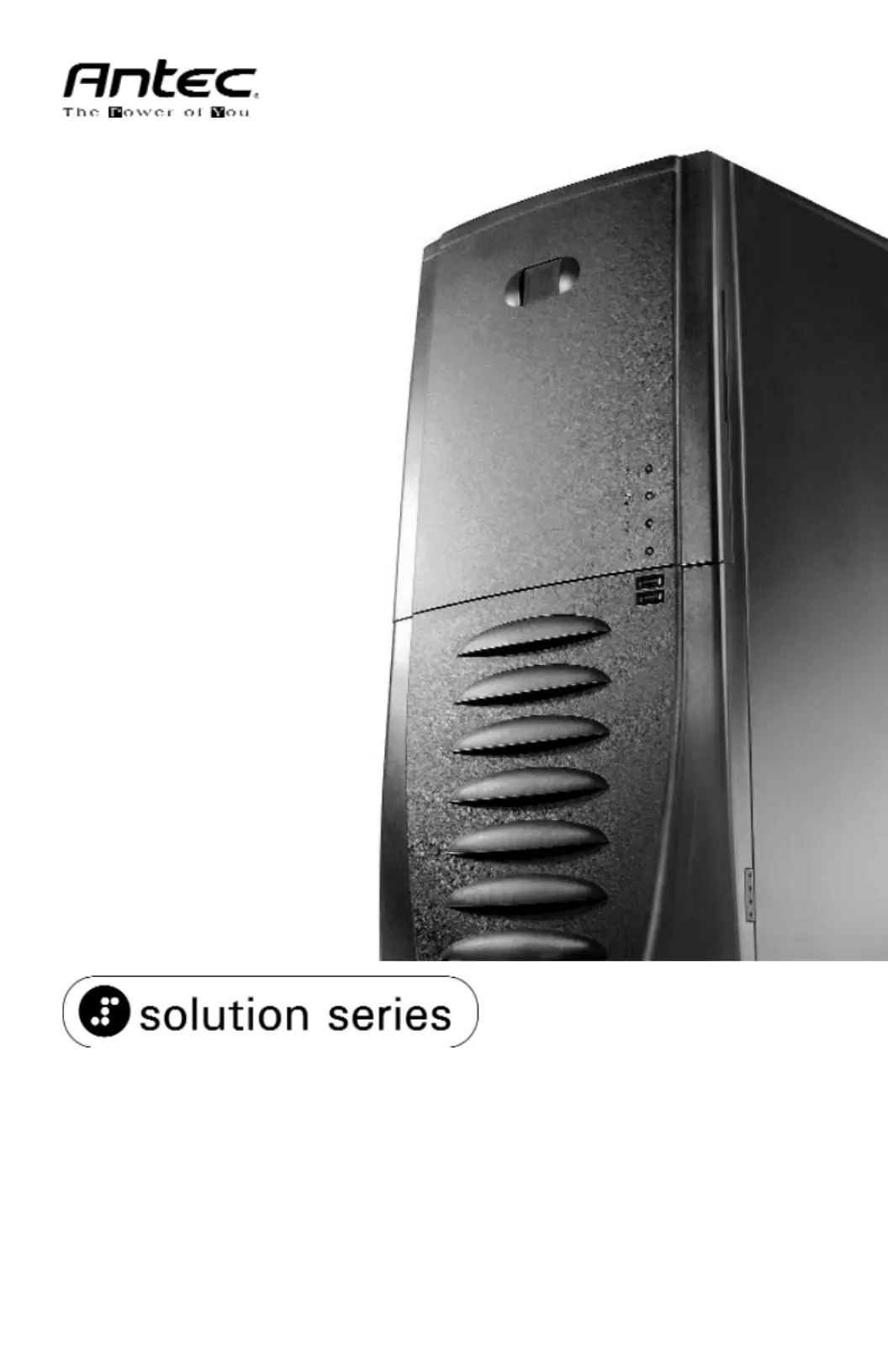
SLK3800B
Produktspecifikationer
| Varumärke: | Antec |
| Kategori: | Computerbehuizing |
| Modell: | Solution SLK3800B |
Behöver du hjälp?
Om du behöver hjälp med Antec Solution SLK3800B ställ en fråga nedan och andra användare kommer att svara dig
Computerbehuizing Antec Manualer

27 December 2024
15 September 2024
15 September 2024
15 September 2024
15 September 2024
15 September 2024
15 September 2024
15 September 2024
15 September 2024
15 September 2024
Computerbehuizing Manualer
Nyaste Computerbehuizing Manualer
9 April 2025
7 April 2025
5 April 2025
3 April 2025
1 April 2025
1 April 2025
1 April 2025
30 Mars 2025
30 Mars 2025
29 Mars 2025