Axton A601 Bruksanvisning
Läs gratis den bruksanvisning för Axton A601 (18 sidor) i kategorin mottagare. Guiden har ansetts hjälpsam av 2 personer och har ett genomsnittsbetyg på 5.0 stjärnor baserat på 1.5 recensioner. Har du en fråga om Axton A601 eller vill du ställa frågor till andra användare av produkten? Ställ en fråga
Sida 1/18

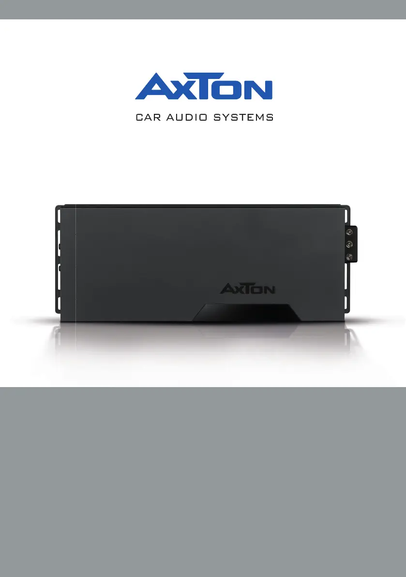
INSTALLATION & OPERATION MANUAL
EINBAU & BEDIENUNGSANLEITUNG
1-/2-/4-/6-CHANNEL POWER AMPLIFIERS
A101 A201 A401 A601III

– –2
Thank you for purchasing this AXTON amplier!
To maximize the performance of this amplier and your complete car audio system installation,
we recommend you acquaint yourself thoroughly with all technical features and controlling
options of this AXTON amplier. Please read this manual carefully, before attempting the
installation.
If, after reading this manual, you still have questions regarding functions or the installation of
the amplier, we recommend that you consult your dealer.
SAFETY INSTRUCTIONS
n Do not turn on any function which may distract you while driving your vehicle.
Functions requiring sustained attention must only be used when the vehicle is at a
complete standstill. Make sure to always stop your vehicle in a safe place before
operating these functions. There are risks of causing an accident.
n Keep the volume at a low level to be able to hear exterior noises while driving
the vehicle. There are risks of causing an accident.
n Do not open the amplier or undertake any modication of the product. There
is a risk of accident, re or electric shock.
n Only use this amplier with 12V mobile applications. Any use other than for this
product intended are may lead to re, electric shock or injury.
n Use correct amperage fuses. There are risks of re or electrocution.
n Do not obstruct radiators and/or vents. Internal overheating may occur and cause
a re.
n Ensure all connections are properly made. Check the section of cable and the
type of cable if it does not correspond with the use. There is a risk of re, injury and/
or damage to the product.
n Do not use screw nuts or fasteners part of the steering or braking systems for
ground connection. The fasteners and nuts used for the brake and steering systems
(or any other security system) as well as various tanks must never be used for
grounding. Use of these parts as ground may deactivate the vehicle’s control system
and cause a re or other technical problem.
n Keep all small objects which could be swallowed, such as the fasteners and
screws, out of the reach of children. Swallowing such objects may cause serious
injuries. In the event of swallowing any of these objects, immediately seek medical
advice.
n Before starting the installation, disconnect the negative terminal of the battery
to avoid any risk of injury, re or damage to the equipment.

– –4
A101 CONNECTIONS + CONTROLS
1 SIGNAL INPUTS R / L
Low-level stereo RCA signal or high-level speaker signal input terminal for connection to
head-unit.
2 INPUT MODE SELECTION
Switch to select the proper input sensitivity range: RCA signal input = Low. Speaker
signal input = Hi.
3 AUTO-TURN-ON MODE
Slide switch to select the auto-turn-on function: REM by remote wire, VOX to switch on
by music signal or DC by DC offset signal of the head units integrated amplier.
4 INPUT SENSITIVITY CONTROL
Input gain potentiometer “SENS” to match the output voltage of the head unit to the
amplier’s input.
5 SUBSONIC HIGHPASS FREQUENCY CONTROL
Control potentiometer to adjust the subsonic highpass ltering frequency point of the
subwoofer output channel.
6 BASS BOOST 0dB to + 18dB
Turn clockwise to get up to + 18dB bass boost or counterclockwise for no boost with a
45 Hz center frequency of the amplied output signal.
7 LOWPASS FREQUENCY CONTROL
Control potentiometer to adjust the lowpass ltering frequency point of the subwoofer
output channel.
8 BASS LEVEL REMOTE CONTROL INPUT
Input terminal to connect the external bass level remote to the amplier.
9 INPUT MODE SELECTION
Switch to select the proper input sensitivity range: RCA signal input = Low. Speaker
signal input = Hi.
10 POWER LED
LED to show the operating status of the amplier by blue/red illumination. Blue is
normal working state, red is protect mode of amplier.
11 SPEAKER OUTPUT TERMINAL
Output terminal to connect the speakers to the amplier.
12 “+12 V” POWER INPUT TERMINAL
Terminal to connect the amplier to the positive +12V pole of the car battery.
13 “REM” INPUT TERMINAL
Terminal to connect the amplier to the automatic (remote) turn-on / turn-off lead of the
head unit. By using the REM terminal, you need to switch the Auto-turn-On mode
3 to
the “REM” position.
14 “GND” POWER INPUT TERMINAL
Terminal to connect the amplier to the chassis ground or negative pole of the car
battery.
Produktspecifikationer
Varumärke: | Axton |
Kategori: | mottagare |
Modell: | A601 |
Färg på produkten: | Zwart |
Vikt: | 110 g |
Bredd: | 111 mm |
Djup: | 65 mm |
Höjd: | 29 mm |
Användarmanual: | Ja |
Kraftkälla: | Batterij/Accu |
Typ av anslutningskontakt: | 3.5mm |
Antal batterier/batterier som stöds: | 2 |
Signal-brusförhållande: | - dB |
Total harmonisk distorsion (THD): | - procent |
Levensduur batterij: | 9 uur |
Batterityp: | AA |
Toppeffekt per kanal: | - W |
Utgångsimpedans: | 10/15 Ohm |
Behöver du hjälp?
Om du behöver hjälp med Axton A601 ställ en fråga nedan och andra användare kommer att svara dig
mottagare Axton Manualer
3 Oktober 2024
12 September 2024
12 September 2024
10 September 2024
9 September 2024
9 September 2024
8 September 2024
8 September 2024
8 September 2024
7 September 2024
mottagare Manualer
- WyreStorm
- PAC
- Manley
- Kopul
- KanexPro
- Hifonics
- Wavtech
- JL Audio
- Bellari
- Ebode
- Blaupunkt
- Simaudio
- Aquatic AV
- Reely
- TechLogix Networx
Nyaste mottagare Manualer
14 Juni 2025
13 Juni 2025
13 Juni 2025
13 Juni 2025
13 Juni 2025
13 Juni 2025
12 Juni 2025
12 Juni 2025
12 Juni 2025
11 Juni 2025