Bixolon SMP6200II Bruksanvisning
Bixolon Inte kategoriserad SMP6200II
Läs gratis den bruksanvisning för Bixolon SMP6200II (5 sidor) i kategorin Inte kategoriserad. Guiden har ansetts hjälpsam av 43 personer och har ett genomsnittsbetyg på 4.3 stjärnor baserat på 4 recensioner. Har du en fråga om Bixolon SMP6200II eller vill du ställa frågor till andra användare av produkten? Ställ en fråga
Sida 1/5
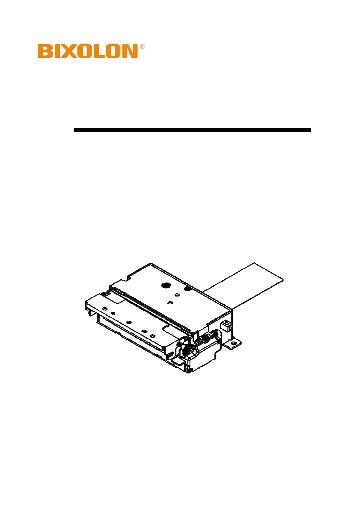
User’s Manual
SMP6200II
Thermal Printer Mechanism
Rev. 1.00
http://www.bixolon.com
Produktspecifikationer
| Varumärke: | Bixolon |
| Kategori: | Inte kategoriserad |
| Modell: | SMP6200II |
Behöver du hjälp?
Om du behöver hjälp med Bixolon SMP6200II ställ en fråga nedan och andra användare kommer att svara dig
Inte kategoriserad Bixolon Manualer

8 Februari 2025
8 Februari 2025
25 September 2024
24 September 2024
24 September 2024
24 September 2024
23 September 2024
23 September 2024
3 September 2024
2 September 2024
Inte kategoriserad Manualer
Nyaste Inte kategoriserad Manualer
9 April 2025
9 April 2025
9 April 2025
9 April 2025
9 April 2025
9 April 2025
9 April 2025
9 April 2025
9 April 2025
9 April 2025