Broan 679 Bruksanvisning
Broan hushålls fläkt 679
Läs gratis den bruksanvisning för Broan 679 (4 sidor) i kategorin hushålls fläkt. Guiden har ansetts hjälpsam av 20 personer och har ett genomsnittsbetyg på 4.8 stjärnor baserat på 6 recensioner. Har du en fråga om Broan 679 eller vill du ställa frågor till andra användare av produkten? Ställ en fråga
Sida 1/4
1
FAN/LIGHT COMBINATION VENTILATORS
MODELS 678 • 679
WARNING
TO REDUCE THE RISK OF FIRE, ELECTRIC SHOCK, OR INJURY TO
PERSONS, OBSERVE THE FOLLOWING
:
1. Use this unit only in the manner intended by the manufacturer. If you
have questions, contact the manufacturer at the address or telephone
number listed in the warranty.
2. Before servicing or cleaning unit, switch power off at service panel and
lock the service disconnecting means to prevent power from being
switched on accidentally. When the service disconnecting means cannot
be locked, securely fasten a prominent warning device, such as a tag, to
the service panel.
3. Installation work and electrical wiring must be done by a qualifi ed
person(s) in accordance with all applicable codes and standards, including
fi re-rated construction codes and standards.
4. Suffi cient air is needed for proper combustion and exhausting of gases
through the fl ue (chimney) of fuel burning equipment to prevent back-
drafting. Follow the heating equipment manufacturer’s guideline and
safety standards such as those published by the National Fire Protection
Association (NFPA), and the American Society for Heating, Refrigeration
and Air Conditioning Engineers (ASHRAE), and the local code authorities.
5. When cutting or drilling into wall or ceiling, do not damage electrical
wiring and other hidden utilities.
6. Ducted fans must always be vented to the outdoors.
7. If this unit is to be installed over a tub or shower, it must be marked as
appropriate for the application and be connected to a GFCI (Ground Fault
Circuit Interrupter) - protected branch circuit.
8. Never place a switch where it can be reached from a tub or shower.
9. Fluorescent models only: Do not use a dimmer switch to control the
light of this unit.
10. This unit must be grounded.
READ AND SAVE THESE INSTRUCTIONS
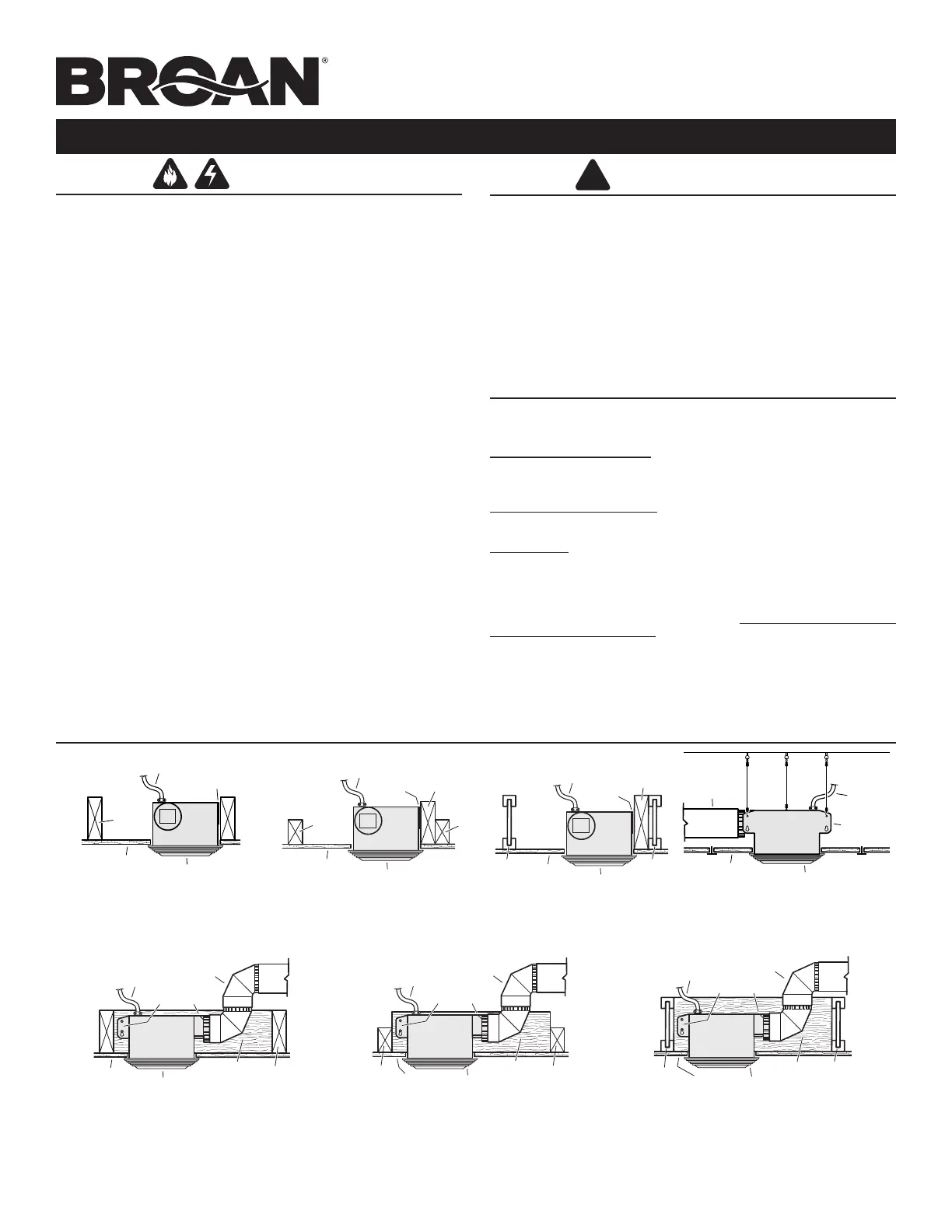
TYPICAL INSTALLATIONS
HOUSING
CEILING
JOIST
MOUNTING TABS
GRILLE
CEILING
MATERIAL
POWER CABLE
HOUSING
CEILING
JOIST
MOUNTING TABS
GRILLE
CEILING
MATERIAL
POWER CABLE
4" ROUND
DUCT
ADDITIONAL
FRAMING
HOUSING MOUNTED TO ADDITIONAL FRAMING
Discharge 90 to joists.
HOUSING MOUNTED DIRECTLY TO JOIST
2 x 6 (or larger)
Discharge parallel to joists.
HOUSING
2 x 4
CEILING
JOIST or
TRUSS
MOUNTING
TABS
CEILING
MATERIAL
POWER CABLE
ADDITIONAL
FRAMING
2 x 4
CEILING
JOIST or
TRUSS
GRILLE
HOUSING MOUNTED TO 2 x 4 TRUSS
Requires additional framing
for mounting tabs.
Discharge parallel to joists.
HOUSING
2 x 4
CEILING
JOIST or
TRUSS
MOUNTING TABS
CEILING
MATERIAL
POWER CABLE
4" ROUND
DUCT
ADDITIONAL
FRAMING
2 x 4
CEILING
JOIST or
TRUSS
GRILLE
HOUSING MOUNTED TO 2 x 4 TRUSS
Requires additional framing for mounting tabs.
Discharge 90 to joists.
HOUSING
MOUNTING TABS
CEILING
MATERIAL
POWER CABLE
4" ROUND
DUCT
ADDITIONAL
FRAMING
"
I
"
JOIST
"
I
"
JOIST
GRILLE
HOUSING MOUNTED TO “I” JOIST
Requires additional framing for mounting tabs.
Discharge 90 to joists.
*Additional framing must be a 2 x 6
(minimum height).
*
*
*
*
HOUSING
MOUNTING
TABS
CEILING
MATERIAL
POWER CABLE
ADDITIONAL
FRAMING
"
I
"
JOIST
"
I
"
JOIST
GRILLE
HOUSING MOUNTED TO “I” JOIST
Requires additional framing
for mounting tabs.
Discharge parallel to joists.
*
USE AND CARE
WARNING: DISCONNECT ELECTRICAL POWER SUPPLY AND LOCK OUT SERVICE
PANEL BEFORE CLEANING OR SERVICING THIS UNIT.
BULB REPLACEMENT
Remove lens by gently depressing sides and pull down.
Use 100 Watt maximum incandescent bulb.
MOTOR LUBRICATION
The motor is permanently lubricated. Do not oil or disassemble motor.
CLEANING
TO CLEAN LENS AND GRILLE:
Remove light lens and bulb. Remove nut in center of refl ector and lower assembly.
CAUTION:Grille and re ector are separate units. Unplug light from WHITE receptacle.
Plastic parts can be cleaned with mild, soapy water (use a mild detergent, such
as dishwashing liquid) and dried with a soft cloth. Do not use abrasive cloth, steel
wool pads, or scouring powders.
TO CLEAN FAN ASSEMBLY:
Unplug fan assembly (BLACK receptacle). To remove motor plate: Find the single tab on the
motor plate (located next to the receptacles). Push up near motor plate tab while pushing
out on side of housing. Or insert a straight-blade screwdriver into slot in housing (next to
tab) and twist screwdriver. Gently vacuum fan, motor and interior of housing. METAL AND
ELECTRICAL PARTS SHOULD NEVER BE IMMERSED IN WATER.
!
CAUTION
1. For general ventilating use only. Do not use to exhaust hazardous or
explosive materials and vapors.
2. This product is designed for ceiling installation only. This product is
designed for installation in ceilings up to a 12/12 pitch. Ductwork must
point up. DO NOT MOUNT THIS PRODUCT IN A WALL.
3. To avoid motor bearing damage and noisy and/or unbalanced impellers,
keep drywall spray, construction dust, etc. off power unit.
4. Please read specifi cation label on product for further information and
requirements.
Installer: Leave this manual with the homeowner.
MOUNTING
TAB
GRILLE
SUSPENDED
CEILING MATERIAL
POWER
CABLE
4" ROUND
DUCT
HOUSING
SUSPENDED CEILINGS
Housing hung with wires - 3-point mount.
99045987C
Produktspecifikationer
| Varumärke: | Broan |
| Kategori: | hushålls fläkt |
| Modell: | 679 |
Behöver du hjälp?
Om du behöver hjälp med Broan 679 ställ en fråga nedan och andra användare kommer att svara dig
hushålls fläkt Broan Manualer

29 September 2025
29 September 2025
29 September 2025
29 September 2025
29 September 2025
28 September 2025
28 September 2025
28 September 2025
28 September 2025
28 September 2025
hushålls fläkt Manualer
Nyaste hushålls fläkt Manualer
1 April 2026
1 April 2026
26 Mars 2026
26 Mars 2026
25 Mars 2026
25 Mars 2026
24 Mars 2026
23 Mars 2026
22 Mars 2026
22 Mars 2026