Bunn CWTF15-APS Bruksanvisning

Bunn kaffebryggare CWTF15-APS

Läs gratis den bruksanvisning för Bunn CWTF15-APS (59 sidor) i kategorin kaffebryggare. Guiden har ansetts hjälpsam av 12 personer och har ett genomsnittsbetyg på 5.0 stjärnor baserat på 6.5 recensioner. Har du en fråga om Bunn CWTF15-APS eller vill du ställa frågor till andra användare av produkten? Ställ en fråga

Sida 1/59
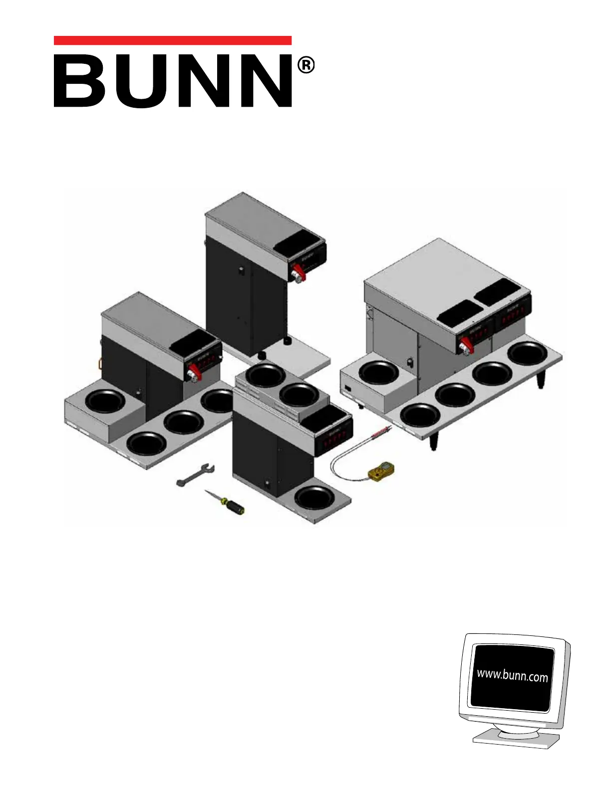
SERVICE & REPAIR MANUAL
BUNN-O-MATIC CORPORATION
POST OFFICE BOX 3227
SPRINGFIELD, ILLINOIS 62708-3227
PHONE: (217) 529-6601 FAX: (217) 529-6644
41711.0001B 05/12 ©2009 Bunn-O-Matic Corporation
C, CS, CT, CWTF,
CRT, CRTF Series
Including
DV, MV, APS/TC/TS,
Single CW & Twins
Supercedes Service Manual: 41711.0000
Page 2 41711.1 030912
BUNN-O-MATIC COMMERCIAL PRODUCT WARRANTY
Bunn-O-Matic Corp. (“BUNN”) warrants equipment manufactured by it as follows:
1) Airpots, thermal carafes, decanters, GPR servers, iced tea/coffee dispensers, MCP/MCA pod brewers thermal servers
and Thermofresh servers (mechanical and digital)- 1 year parts and 1 year labor.
2) All other equipment - 2 years parts and 1 year labor plus added warranties as specified below:
a) Electronic circuit and/or control boards - parts and labor for 3 years.
b) Compressors on refrigeration equipment - 5 years parts and 1 year labor.
c) Grinding burrs on coffee grinding equipment to grind coffee to meet original factory screen sieve analysis - parts
and labor for 4 years or 40,000 pounds of coffee, whichever comes first.
These warranty periods run from the date of installation BUNN warrants that the equipment manufactured by it will be
commercially free of defects in material and workmanship existing at the time of manufacture and appearing within the
applicable warranty period. This warranty does not apply to any equipment, component or part that was not manufactured
by BUNN or that, in BUNN’s judgment, has been affected by misuse, neglect, alteration, improper installation or operation,
improper maintenance or repair, non periodic cleaning and descaling, equipment failures related to poor water quality,
damage or casualty. In addition, the warranty does not apply to replacement of items subject to normal use including but
not limited to user replaceable parts such as seals and gaskets. This warranty is conditioned on the Buyer 1) giving BUNN
prompt notice of any claim to be made under this warranty by telephone at (217) 529-6601 or by writing to Post Office
Box 3227, Springfield, Illinois 62708-3227; 2) if requested by BUNN, shipping the defective equipment prepaid to an
authorized BUNN service location; and 3) receiving prior authorization from BUNN that the defective equipment is under
warranty.
THE FOREGOING WARRANTY IS EXCLUSIVE AND IS IN LIEU OF ANY OTHER WARRANTY, WRITTEN OR ORAL, EX-
PRESS OR IMPLIED, INCLUDING, BUT NOT LIMITED TO, ANY IMPLIED WARRANTY OF EITHER MERCHANTABILITY
OR FITNESS FOR A PARTICULAR PURPOSE. The agents, dealers or employees of BUNN are not authorized to make
modifications to this warranty or to make additional warranties that are binding on BUNN. Accordingly, statements by such
individuals, whether oral or written, do not constitute warranties and should not be relied upon.
If BUNN determines in its sole discretion that the equipment does not conform to the warranty, BUNN, at its exclusive op-
tion while the equipment is under warranty, shall either 1) provide at no charge replacement parts and/or labor (during the
applicable parts and labor warranty periods specified above) to repair the defective components, provided that this repair
is done by a BUNN Authorized Service Representative; or 2) shall replace the equipment or refund the purchase price for
the equipment.
THE BUYER’S REMEDY AGAINST BUNN FOR THE BREACH OF ANY OBLIGATION ARISING OUT OF THE SALE OF THIS
EQUIPMENT, WHETHER DERIVED FROM WARRANTY OR OTHERWISE, SHALL BE LIMITED, AT BUNN’S SOLE OPTION
AS SPECIFIED HEREIN, TO REPAIR, REPLACEMENT OR REFUND.
In no event shall BUNN be liable for any other damage or loss, including, but not limited to, lost profits, lost sales, loss of
use of equipment, claims of Buyer’s customers, cost of capital, cost of down time, cost of substitute equipment, facilities
or services, or any other special, incidental or consequential damages.
392, AutoPOD, AXIOM, BrewLOGIC, BrewMETER, Brew Better Not Bitter, BrewWISE, BrewWIZARD, BUNN Espress, BUNN
Family Gourmet, BUNN Gourmet, BUNN Pour-O-Matic, BUNN, BUNN with the stylized red line, BUNNlink, Bunn-OMatic,
Bunn-O-Matic, BUNNserve, BUNNSERVE with the stylized wrench design, Cool Froth, DBC, Dr. Brew stylized Dr. design,
Dual, Easy Pour, EasyClear, EasyGard, FlavorGard, Gourmet Ice, Gourmet Juice, High Intensity, iMIX, Infusion Series, In-
tellisteam, My Café, Phase Brew, PowerLogic, Quality Beverage Equipment Worldwide, Respect Earth, Respect Earth with
the stylized leaf and coffee cherry design, Safety-Fresh, savemycoffee.com, Scale-Pro, Silver Series, Single, Smart Funnel,
Smart Hopper, SmartWAVE, Soft Heat, SplashGard, The Mark of Quality in Beverage Equipment Worldwide, ThermoFresh,
Titan, trifecta, Velocity Brew, A Partner You Can Count On, Air Brew, Air Infusion, Beverage Bar Creator, Beverage Profit
Calculator, Brew better, not bitter., BUNNSource, Coffee At Its Best, Cyclonic Heating System, Daypart, Digital Brewer
Control, Nothing Brews Like a BUNN, Pouring Profits, Signature Series, Tea At Its Best, The Horizontal Red Line, Ultra are
either trademarks or registered trademarks of Bunn-O-Matic Corporation.
Page 3 41711.1 052009
Contents
Trouble Shooting 4 ..............................................................................................................
Component Access 10 ........................................................................................................
Control Thermostat 10 ........................................................................................................
Electronic Thermostat 11 ....................................................................................................
ON/OFF Switch 12 ...............................................................................................................
Start Switch (Brew) 13 ........................................................................................................
Solenoid (Inlet) 14 ..............................................................................................................
Tank Heater 16 ....................................................................................................................
Fill Basin 16 ........................................................................................................................
Tank Heater Switch 18 ........................................................................................................
Thermal Cut-Off 20 .............................................................................................................
Coil/Faucet 21 .....................................................................................................................
Limit Thermostat 22 ............................................................................................................
Recovery Booster 23 ...........................................................................................................
Timer (Early Model) 24 .......................................................................................................
Freshness Timer (Early Models)..................................................................................... 25
Digital Brew Timer (Late Model) 26 ....................................................................................
Warmer Elements........................................................................................................... 28
Schematic Wiring Diagrams 29 ..........................................................................................
Page 5
TROUBLESHOOTING (cont.)
Brew cycle will not start (cont.)
Water is not hot
PROBABLE CAUSE REMEDY
3. ON/OFF Switch
4. Start Switch
5. Timer
6. Solenoid Valve
7. Water strainer/flow control
(.222 GPM) Early models
1. Tank Heater Switch
2. (A) Limit Thermostat
(B) Thermal Cut-Off (Brewers
with Faucet)
CAUTION - Do not eliminate
or bypass limit thermostat or
thermal cut-off. Use only BOM
replacement parts.
3. Control Thermostat
4. Tank Heater
Refer to Service - ON/OFF
Switch for testing.
Refer to Service - Start Switch
for testing procedures.
Refer to Service - Timer for test-
ing procedures.
Refer to Service - Solenoid Valve
for testing procedures.
(A) Direction of flow arrow must
be pointing towards brewer.
(B) Remove the strainer/flow
control and check for obstruc-
tions. Clear or replace.
Refer to Service - Tank Heater
Switch for testing procedures.
Refer to Service - Limit Ther-
mostat for testing procedures.
Thermal Cut-Off for testing
procedures.
Refer to Service - Control Ther-
mostat for testing procedures.
Refer to Service - Tank Heater
for testing procedures.
PROBLEM
41711.1 052009
Page 7
TROUBLESHOOTING (cont.)
Spitting or excessive steaming
(cont.)
Dripping from sprayhead
Water flows into tank continu-
ously (ON/OFF Switch "ON")
Water flows into tank continu-
ously (ON/OFF Switch "OFF")
Beverage overflows dispenser
2. Control Thermostat
1. Syphon System
2. Lime Build-up
CAUTION - Tank and tank com-
ponents should be delimed
regularly depending on local
water conditions. Excessive min-
eral build-up on stainless steel
surfaces can initiate corrosive
reactions resulting in serious
leaks.
3. Solenoid Valve
1. Timer
1. Solenoid Valve
1.Dispenser
2. Timer
3. Solenoid Valve
Refer to Service - Control Ther-
mostat for testing procedures.
The brewer must be level or
slightly lower in front to syphon
properly.
Inspect the tank assembly for
excessive lime deposits. Delime
as required.
Remove the solenoid valve and
clear any obstructions. Rebuild
or replace the valve if necessary.
Refer to Service - Timer for test-
ing procedures.
Remove the Solenoid Valve and
clean any obstruction. Rebuild
or replace the valve if necessary.
The dispenser must be com-
pletely empty before starting a
brew cycle.
Refer to Service - Timer for test-
ing procedures.
Remove the Solenoid Valve and
clean any obstruction. Rebuild
or replace the valve if necessary.
PROBLEM PROBABLE CAUSE REMEDY
41711.1 052009
Page 8
TROUBLESHOOTING (cont.)
Weak beverage
Dry coffee grounds remain in
the funnel
Brewer is making unusal noises
1. Filter Type
2. Coffee Grind
3. Sprayhead
4. Funnel Loading
5. Water Temperature
1. Funnel Loading
1. Solenoid
2. Plumbing Lines
3. Water Supply
PROBLEM PROBABLE CAUSE
BUNN® paper filters must be used
for proper extraction.
A fine or drip grind must be used
for proper extraction.
A six-hole stainless steel spray-
head must be used for proper
extraction.
The BUN paper filter must be
centered in the funnel and the
bed of ground leveled by gentle
shaking.
Place an empty funnel on an empty
dispenser beneath the sprayhead.
Initiate a brew cycle and check the
water temperature immediately
below the sprayhead with a ther-
mometer. The reading should not
be less than 195°F (76°C). Adjust
the control thermostat to increase
the water temperature. Replace if
necessary.
The BUN paper filter must be
centered in the funnel and the
bed of grounds leveled by gently
shaking.
The nut on the solenoid must
be tight or it will vibrate during
operation.
Plumbing lines should not resting
on the counter top.
(A) The brewer must be connected
to a cold water line.
(B) Water pressure to the brewer
must not exceed 90 psi (620 kPa).
Install a regulator if necessary to
lower the working pressure to ap-
proximately 50 psi (345 kPa).
REMEDY
41711.1 052009
Page 9
TROUBLESHOOTING (cont.)
Brewer is making unusal noises
(cont.)
Low beverage serving tempera-
ture
4. Tank Heater
1. Warmer
2. ON/OFF Switch
Remove and clean lime off the
tank heater.
Refer to Service - Warmer ele-
ment for testing procedures.
Refer to Service - ON/OFF
Switch for testing procedures.
PROBLEM PROBABLE CAUSE REMEDY
41711.1 052009
Page 10
SERVICE
This section provides procedures for testing and
replacing various major components used in this
brewer should service become necessary. Refer to
Troubleshooting for assistance in determining the
cause of any problem.
WARNING - Inspection, testing, and repair of electri-
cal equipment should be performed only by qualified
service personnel. The brewer should be unplugged
when servicing, except when electrical tests are re-
quired and the test procedure specifically states to
plug-in the brewer.
COMPONENT ACCESS
WARNING - Disconnect the brewer from the power
source before the removal of any panel or the replace-
ment of any component.
All components are accessible by the removal of
the top cover, front inspection panel, warmer plate(s)
and rear utility cover (Twins only).
CONTROL THERMOSTAT
FIG. 10-1 CONTROL THERMOSTAT
Location:
The control thermostat is located inside the trunk
on the upper left side of the component bracket.
Test Procedures:
1. Disconnect the brewer from the power source.
2. Disconnect the leads from control thermostat.
41711.1 052009
3. Gently remove the capillary bulb and grommet
from the tank.
4. Check for continuity across the thermostat termi-
nals. The indication must be:
a) Continuity with knob rotated fully clockwise.
b) No continuity with knob rotated fully counter-
clockwise. NOTE: First style does not have the ON/
OFF feature, simply check continuity.
If continuity is not present as described, replace control
thermostat.
If continuity is present as described, refer to the wiring
diagrams and check the brewer wiring harness.
Removal and Replacement:
1. Disconnect the control thermostat wires.
2. Remove the thermostat capillary bulb by firmly
pulling up on the capillary at the tank lid. This will
disengage the grommet from the tank lid.
3. Remove the one #8-32 screw securing the control
thermostat to the component bracket inside the
trunk.
4. Slide the grommet to the line 4.5" above the bulb
on the new capillary tube.
5. Insert the capillary bulb through the hole in the
tank lid and press the grommet firmly and evenly
so that the groove in the grommet ts into the tank
lid.
6. Carefully bend the capillary tube so that the tube
and bulb inside the tank are in the vertical posi-
tion.
NOTE - The capillary tube must be clear of any electri-
cal termination and not kinked.
7. Using #8-32 screw(s), secure the control thermo-
stat to the component bracket inside the trunk.
8. For first type thermostat, refer to Wiring Diagrams
when reconnecting thermostat wires.
9. Adjust the control thermostat as required.
NOTE: First type will only turn approximately one
turn. Clockwise to the stopper is approximately
180° F, maximum clockwise to stopper is counter
approximately 200° F.
Later types will be approximately 200 F when °
turned maximum clockwise. Turning it counter-
clockwise until it clicks will turn off (open con-
tacts).
Page 11
SERVICE (cont.)
OPTIONAL ELECTRONIC THERMOSTAT (ERT):
The ERT is located inside the trunk on the upper left
side of the component bracket.
Test Procedures:
1. Disconnect the brewer from the power source.
2. Gently remove the temperature sensor and grom-
met from the tank.
3. Check voltage across the blue wire from limit
thermostat and the white wire at the terminal
block. Connect the brewer to the power source.
The indication must be: 120Vac.
If voltage is not present as described, refer to the wiring
diagrams and check the brewer wiring harness
If voltage is present as described, proceed to #4.
4. Disconnect the brewer from the power source.
5. With the temperature sensor and grommet still out
of the tank, check voltage across the black wire
to the heater and the white wire at the terminal
block. Connect the brewer to the power source.
The indication must be: 120Vac.
If voltage is not present as described, replace ERT.
If voltage is present as described, the ERT is function-
ing properly.
Removal and Replacement:
1. Disconnect the control thermostat wires.
2. Remove the temperature sensor by rmly pulling-
up on the metal sheath at the tank lid. This will
disengage the grommet from the tank lid.
3. Remove the one #8-32 screw securing the ERT to
the component bracket inside the trunk.
4. Slide the grommet to the top of the sheath.
5. Insert the temperature sensor through the hole
in the tank lid and press the grommet firmly and
evenly so that the groove in the grommet fits into
the tank lid.
6. Using the #8-32 screw, secure the ERT to the
component bracket inside the trunk.
7. For first type thermostat, refer to Wiring Diagrams
when reconnecting ERT wires.
8. Adjust the ERT as required.
FIG 11-1 THERMOSTAT TERMINALS
First Type Second Type
Third Type
41711.1 052009
ERT
NOTE: ° ° The ERT has a range of 170 - 210 F. Use care
not to set it too high or boiling could occur.
Page 13
SERVICE (cont.)
START SWITCHES
Location: CRT/CRTF
On brewers w/out fresh light, the start switch is
located in the right front of the hood.
On brewers w/fresh light, the start switch is located
on the right side of the hood.
Location: CT/CWT/CWTF/TWINS
On most "CT" series brewers, the start switch is
located in the front of the hood.
On some "convertible" or "CS" brewers, the start
switch is located on either the right or left side of the
hood.
NOTE: Optional on the left and right side warmer
housings on 0/6 TWINS, connected in parallel to front
mounted start switches.
Test Procedure:
1. Disconnect the brewer from the power supply.
2. Disconnect the blue wire and the white/red wire
from the switch terminals.
3. Check for continuity across the two terminals on
the switch when it is held in the "pressed-in" posi-
tion. Continuity must not be present across these
terminals in the released position.
If continuity is present as described, reconnect the blue
wire and the white/red to the switch terminals.
If continuity is not present as described, replace the
switch.
Removal and Replacement:
1. Remove the blue wire and white/red from the start
switch.
2. Remove round retaining nut from the front of
the switch and remove switch and internal tooth
lockwasher from the inside of the hood.
3. Push new switch with internal tooth lockwasher
through the hole in the hood and secure with round
retaining nut.
4. Refer to Fig. 11 when reconnecting the wires.
FIG. 13-1 START SWITCH
FIG. 13-2 START SWITCH TERMINALS
BLU to Timer P1
WHI/RED to
Timer P3
(3) WHI to Neutral or RED to L2
(2)BLKtoL1
START SWITCH
CT SERIES
CRT/CRTF
CRT/CRTF
CT/CWT/CWTF/TWINS
41711.1 052009
Page 14
SERVICE (cont.)
SOLENOID VALVES
Location:
The solenoid valve is located inside the trunk on
the lower center part of the component bracket.
Test Procedures:
1. Disconnect the brewer from the power source.
2. Disconnect the white and black wires from the
solenoid valve. With the "ON/OFF" switch in the
"ON" upper position press the start switch.
3. Check the voltage across the white and black wires
with a voltmeter. Connect the brewer to the power
source. The indication must be:
a) 120 volts ac for two wire 120 volt models and
three wire 120/240 volt models.
b) 200 to 240 volts ac for two wire 200 or 240 volt
models.
4. Disconnect the brewer from the power source,
If voltage is present as described, proceed to #5
If voltage is not present as described, refer to Wiring
Diagrams and check brewer wiring harness.
5. Check for resistance across the solenoid valve coil
terminals.
If resistance is present as described, reconnect the
white and black wire from the timer.
If resistance is not present as described, replace the
solenoid valve.
6. Check the solenoid valve for coil action. Connect
the brewer to the power source. With "ON/OFF"
switch in the "ON' upper position press start switch
and listen carefully in the vicinity of the solenoid
valve for a" clicking" sound as the coil magnet
attracts.
7. Disconnect the brewer from the power source.
If the sound is heard as described and water will not
pass through the solenoid valve, there may be a block-
age in the water line before the solenoid valve or, the
solenoid valve may require inspection for wear, and
removal of waterborne particles.
If the sound is not heard as described, replace the
solenoid valve.
Removal and Replacement:
1. Remove the white and black from the solenoid
valve.
2. Turn off the water supply to the brewer.
3. Disconnect the water lines to and from the solenoid
valve.
4. Remove the two #8-32 screws securing the sole-
noid mounting bracket to the component bracket.
Remove solenoid bracket and solenoid valve as an
assembly.
5. Remove the two #10-32 screws and lockwash-
ers securing the solenoid valve to the solenoid
bracket.
6. Using two #10-32 screws and lockwashers in-
stall new solenoid valve on solenoid mounting
bracket.
7. Using two #8-32 screws install solenoid valve and
bracket to the component bracket.
8. Securely fasten the water lines to and from the
solenoid valve.
9. Refer to Fig. 9 when reconnecting the wires.
FIG. 14-1 SOLENOID VALVE
FIG. 14-2 SOLENOID VALVE TERMINALS
WHI from Timer
BLKfromTimer
41711.1 052009
EARLY MODELS LATE MODELS
Page 15 41711.1 052009
120VAC-1.18K
240VAC-3.76K
120VAC - 247
240VAC - 757
120VAC - 334
SERVICE (cont.)
SOLENOID VALVES
Disassembly:
1. Use of the basin wrench 01060.0000 is recom-
mended for disassembly of early style valves as
illustrated below.
2. Disconnect from power source and turn off the
water supply to the brewer.
3. Disconnect the water lines to and from the solenoid
valve.
4. Remove the two #8-32 screws securing the sole-
noid mounting bracket to the component bracket.
Remove solenoid bracket and solenoid valve as an
assembly.
5. Remove the two #10-32 screws and lock wash-
ers securing the solenoid valve to the solenoid
bracket.
6. Disassemble the valve according to the illustrations
that correspond to the particular valve you have.
7. On early style valves, leave the fittings installed
in the base to use as leverage. DO NOT CLAMP
THE BASE WITH LOCKING PLIERS AS THIS CAN
CAUSE DAMAGE!
8. Refer to Illustrated Parts Catalogs for replacement
solenoids and repair/rebuild kits.
FIG. 15-1 FIRST STYLE FIG. 15-2 THIRD STYLE
FIG. 15-2 SECOND STYLE


Produktspecifikationer

Varumärke: Bunn
Kategori: kaffebryggare
Modell: CWTF15-APS

Behöver du hjälp?

Om du behöver hjälp med Bunn CWTF15-APS ställ en fråga nedan och andra användare kommer att svara dig