Curtis enGage III Bruksanvisning
Curtis ej kategoriserat enGage III
Läs gratis den bruksanvisning för Curtis enGage III (2 sidor) i kategorin ej kategoriserat. Guiden har ansetts hjälpsam av 24 personer och har ett genomsnittsbetyg på 4.6 stjärnor baserat på 8 recensioner. Har du en fråga om Curtis enGage III eller vill du ställa frågor till andra användare av produkten? Ställ en fråga
Sida 1/2
1.0 Technical Specifications
1.1 Electrical
Operating Voltage Range: +/– 25% of nominal voltage.
Operating Current Range: Values below reflect keyswitch in “on” position.
*Maximum current draw listed based upon all icons illuminated. Each icon draws 15mA.
1.2 Mechanical
Display: LCD with 10-segment bar and 5 digit numeric (5mm high).
Hour Meter Range & Resolution: 9,999.9 Maintenance Hours;
99,999 Total Hours
Panel Cutout: 45 x 92 mm rectangular.
1.3 Environmental
Shock: SAE J 1378 Amplitude.
44-55 g, half sine, 9-13 ms duration.
Vibration: SAE J 1378 Double amplitude of 1.53mm with frequency sweep for
10-80-10 Hz (20 g max) at 1 minute intervals.
Operating Temp.: –40˚C to +85˚C
Storage Temp.: –50˚C to +90˚C
Humidity: 95% RH (non-condensing)
IP Rating: 65 Front & Rear with AMP connector installed.
65 Front, 40 Rear with Molex connector installed.
2.0 Installation
2.1 Terminal Assignments
Information is for standard design units only. Customers should review specific
diagrams for custom units.
2.2 Typical Wiring Diagrams
See wiring schematic drawings on reverse side of page.
2.3 Mounting
Curtis enGage® III is mounted in a 45X92 mm rectangular cutout. In addition to the
snap-fit case design, an optional mounting bracket is available.
2.4 Interconnect
Curtis enGage® III is available with AMP (8 pin & 10 pin) or Molex (8 pin & 10 pin)
connectors. See complete drawing with notes on reverse side of page for specific
part numbers.
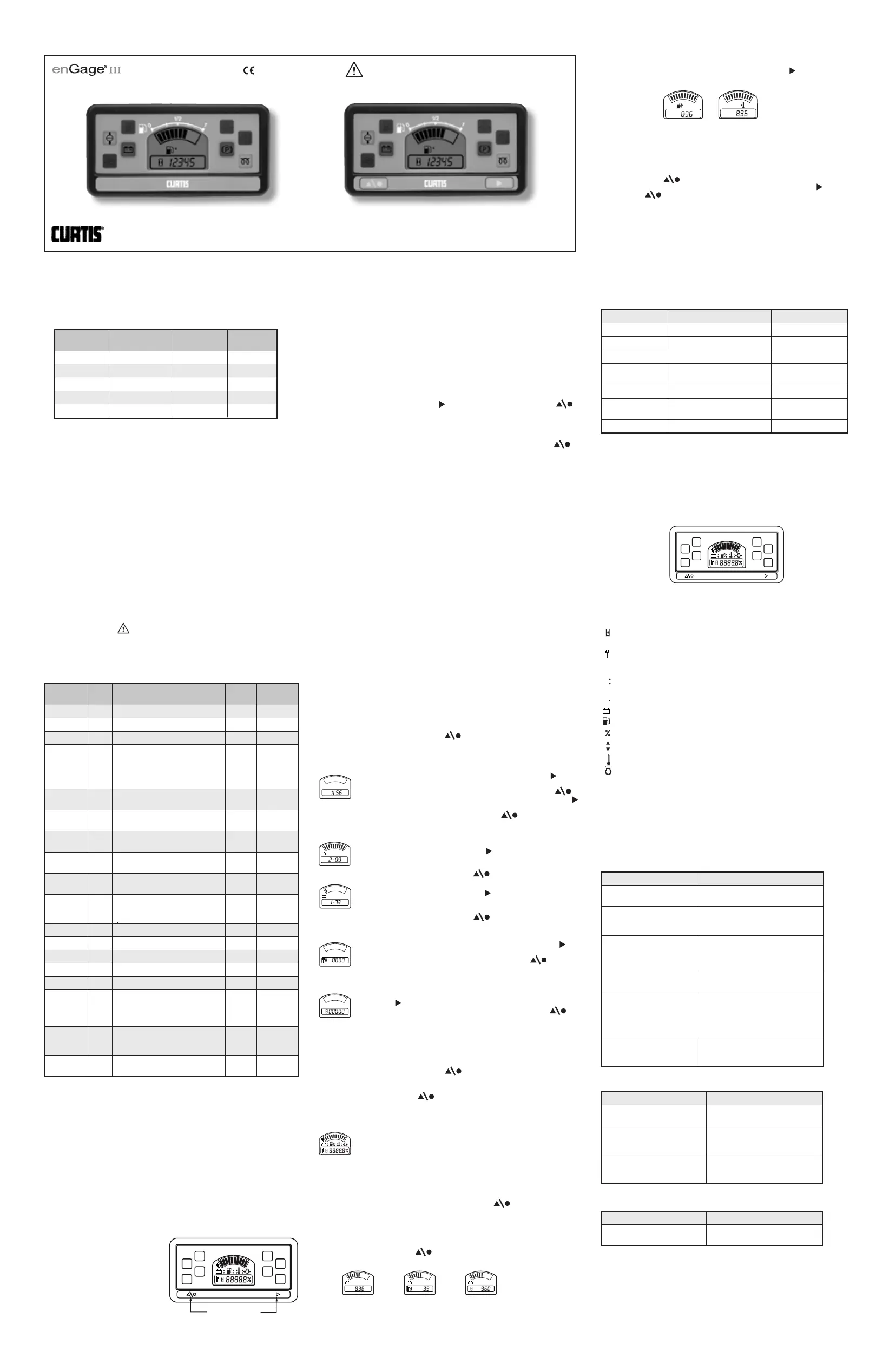
2.5 Product Identification
2.5.1 Programmable vs. Factory Set Instruments
Curtis enGage® III is available with
or without front panel buttons.
Gauges without buttons are factory
set and cannot be adjusted.
Gauges with buttons have field
adjustable parameters and can be
programmed per section 2.6.
2.5.2 Curtis enGage® III & Multifunction Design
Curtis enGage® III products can be configured in a variety of ways to maximize
customer value and efficiency. The instruction manual covers a broad spectrum of
products. Please note that some sections of the instructions may refer to functions
not included in your instrument.
2.6 Configuring Your Gauge
Access to these operations is sequential in this order. Adjustments of the following
functions can be performed in the Configuration Mode:
1. Time-of-Day Clock
2. Battery Discharge Indicator (BDI) profiles
3. Maintenance interval
4. Settable hour meter
During configuration, the right button is used to increment. The left button
is used to:
1. Enter a selection.
2. Advance to the next configurable item.
If no change is desired to a specific gauge function, continue to press the left
button until the next desired function is reached.
The time-of-day clock is entered by setting the hours digits between 01 and 12, then
“minutes” digits between “00” and “59”.
The profile of the BDI is settable with the front panel buttons. The Discharge Full
profile (when the gauge will begin calculating ‘discharge’) is adjustable from 1.80
through 2.30 volts per cell (VPC) in 0.01 VPC increments. The Discharge Empty
profile (when the gauge will indicate ‘empty’) is adjustable from 1.50 through 2.20
VPC in 0.01 VPC increments.
The maintenance interval (when the gauge signals that maintenance is due) is
configurable and should be set after the initial installation. The interval can be set
between 1 and 9,999 hours in 1 hour increments.
The settable hour meter can be set to any value between 0 and 99,999 hours. When
the gauge is operational, the total hour meter will begin from this value.
Configuration Notes:
The gauge remains in configuration mode for 30 seconds without input from the user.
When configuring each function (time-of-day, maintenance interval, etc.), you must
enter in all data for that function for it to be saved. If incomplete data is entered for
a function and the programming mode is timed out (after 30 seconds of no input
received by the gauge), the gauge will revert back to what was previously stored for
that item.
If you interrupt the data entry process in the Configuration Mode, the gauge saves
data in those sections already completed. To complete configuration, re-enter
configuration mode (2.6.1) and simply toggle past the completed sections and
resume where you left off.
2.6.1 Entering Configuration Mode
1. Apply main power (9-60VDC) to V+, V–.
2. Apply V+ (9-60 VDC) to Keyswitch Input.
3. Apply V+ (9-60 VDC) to Set-up Enable.
4. Press and hold the left button on the front panel until the entire
display flashes and then release.
2.6.2 Setting the Time-of-Day Clock
The display flashes the two “Hours” digits. Press the right button
to increment by one hour, or hold the button to increment continuously.
When the desired number of hours is reached, press the left button
once. The display flashes the two “Minutes” digits. Press the right button
to increment by one minute or hold the button to increment continuously. When the
desired number of minutes is reached, press the left button once.
2.6.3 Setting the Battery Indicator Profiles
The display flashes the three digits of the discharge full profile (factory
setting is 2.09 VPC). Press the right button to increment by 0.01 VPC
or hold the button to increment continuously. When the display reaches
2.30 it will automatically restart at 1.80 VPC. When the desired reset profile
setting is reached, press the left button once.
The display flashes the three digits of the discharge empty profile (factory
setting is 1.73 VPC). Press the right button to increment by 0.01 VPC
or hold the button to increment continuously. When the display reaches
full it will automatically restart at 1.50 VPC. When the desired reset profile
setting is reached, press the left button once.
2.6.4 Setting the Maintenance Interval
The display flashes the left digit (thousands of hours). Press the right
button to increment by one or hold the button to increment continuously.
When the desired number is reached, press the left button
once to proceed to the next digit. Repeat this process for all 4 digits.
2.6.5 Setting the Total Hour Meter
The display flashes the left digit (tens of thousands of hours). Press the
right button to increment by one or hold the button to increment
continuously. When the desired number is reached, press the left
button once to proceed to the next digit. Repeat this process for
all 5 digits.
2.6.6 Exiting Configuration Mode
The configuration mode can be exited in three ways:
1. Press and hold the left button for three seconds.
2. Leave buttons untouched for 30 seconds.
3. Press the left button after selecting the last (right) digit of the last
function available.
3.0 Operation
When the main power (9-60 VDC) is applied to V+ and V–, a power-up
sequence is initiated. All display segments are illuminated for one second.
The display is then turned off until the keyswitch is activated.
3.1 Button Use During Normal Operation
3.1.1 Toggling Display Functions
Should your gauge be so equipped, press the left button to sequentially toggle
between the three numeric gauge functions (time-of-day clock, maintenance hours,
total hours).
The following procedures (3.1.2 and 3.1.3) can be done without V+ applied to Setup
Enable pin.
Press and hold the left button on the front panel until the entire display flashes
and then release.
3.1.2 Toggling Between Bargraph (Upper) Display Functions
Should your gauge be so equipped, press the right hand button to toggle
between the two bargraph displays.
3.1.3 Setting/Changing the Time-of-Day Clock
See Section 2.6.2.
3.1.4 Resetting the Maintenance Hour Meter
Press the left button until the maintenance hour meter function is displayed
(the wrench icon will be illuminated). Press and hold both the right button and
the left button until the display flashes and the maintenance hour meter
is reset to zero. This can be performed at any time, independent of the actual
maintenance status.
3.2 Auto-range
Curtis enGage® III will automatically recognize battery voltage based on the status of
the auto-range input pin.
3.3 Output and Warning LED
3.3.1 LCD Warnings and MOSFET Activation
Curtis enGage® III provides LCD warnings and MOSFET activation as follows:
KEY:RMB= Right Most LCD Bar; LMB= Left Most LCD Bar
3.3.2 LED Warning Icons
Curtis enGage® III provides up to 8 LED based warning icons as shown.
Of the 8 LED icons available, the 4 on the left side of the gauge are controlled by the
microprocessor and are factory programmable. The remaining 4 icons on the right
side are activated by inputs that are switched to ground (see typical wiring diagrams
sec 2.2).
3.4 LCD Icons
Curtis enGage® III uses a number of icons (depending on functions chosen) to assist
the user:
Hourglass Icon: Turned on (not blinking) to indicate that an hour meter is
displayed in the numeric display. Flashes to indicate hour meter accumulation.
Wrench Icon: Turned on (not blinking) to indicate that the maintenance hour
meter is displayed in the numeric display. Flashes when the maintenance
interval is reached.
Colon: Flashes to indicate that the time-of-day clock is being displayed in the
numeric display and that time is counting-up.
Decimal Point: To indicate 1/10 of an hour on the maintenance hour meter
Fuel or Battery Icon: Turned on (not flashing) depending on which function the
gauge is programmed to monitor. It flashes when a low condition is detected.
Percent: Indicates remaining percentage of interval or level.
Up/Down: Indicates whether function is displayed as bargraph or numeric.
Thermometer Icon: Flashes at high temperature condition.
Pressure Icon: Flashes at low and high condition.
3.5 Resetting BDI
OCR—Open Circuit Reset: The BDI will reset when gauge is disconnected from
discharged battery and reconnected to a fully charged battery.
CTR—Charge Tracking Reset: Battery state-of-charge will be tracked by gauge
during any charging period(s).
4.0 Troubleshooting
BDI Function
Sender Function
Maintenance Function
1
0
1
0
1
0
1
0
1
0
1
0
1
0
1
0
1
0
1
0
RED ICON
YELLOW ICON
RED ICON
YELLOW ICON
YELLOW ICON
RED ICON
YELLOW ICON
RED ICON
LCD
8
10
1
1
CONNECTOR J2
CONNECTOR J1
5.5
53.7
46.7
50.0
100.0
L1
L2
L3
L4
L5
L6
L7
L8
PUSHBUTTONS
(IF SO EQUIPPED)
PUSHBUTTONS
(IF SO EQUIPPED)
L1
L2
L3
L4
L5
L6
L7
L8
NOTES:
1) CASE MATERIAL: ABS/PC BLEND, BLACK
2) LENS MATERIAL: POLYCARBONATE
3) PANEL CUTOUT SIZE: 45 +.6/-.0 X 92 +.8/-.0
4) ALL SENDER CHARACTERISTICS TO BE DETERMINED
MOLEX MATING CONNECTORS
J1
J2
CONNECTOR
PIN
MOLEX #39-01-2105
MOLEX #39-00-0039
MOLEX #39-01-2085
AMP #1-794772-0
AMP #794758-1
AMP #784772-8
WIRE SEAL
GASKET
AMP MATING CONNECTORS
J1
J2
AMP #794821-1
AMP #770904-1
AMP #794781-1
L1
L2
L3
L4
L5
L6
L7
L8
1
0
1
0
53035 Rev D 6/10
1
0
1
0
1
0
1
0
1
0
1
0
RED ICON
YELLOW ICON
RED ICON
YELLOW ICON
YELLOW ICON
RED ICON
YELLOW ICON
RED ICON
LCD
8
10
1
1
CONNECTOR J2
CONNECTOR J1
5.5
53.7
46.7
50.0
100.0
L1
L2
L3
L4
L5
L6
L7
L8
PUSHBUTTONS
(IF SO EQUIPPED)
PUSHBUTTONS
(IF SO EQUIPPED)
L1
L2
L3
L4
L5
L6
L7
L8
NOTES:
1) CASE MATERIAL: ABS/PC BLEND, BLACK
2) LENS MATERIAL: POLYCARBONATE
3) PANEL CUTOUT SIZE: 45 +.6/-.0 X 92 +.8/-.0
4) ALL SENDER CHARACTERISTICS TO BE DETERMINED
MOLEX MATING CONNECTORS
J1
J2
CONNECTOR
PIN
MOLEX #39-01-2105
MOLEX #39-00-0039
MOLEX #39-01-2085
AMP #1-794772-0
AMP #794758-1
AMP #784772-8
WIRE SEAL
GASKET
AMP MATING CONNECTORS
J1
J2
AMP #794821-1
AMP #770904-1
AMP #794781-1
L1
L2
L3
L4
L5
L6
L7
L8
Switched to
Ground
Factory
Programmable
Read Instructions Carefully!
®
Without buttonsWith buttons
CURTIS INSTRUMENTS, INC.200 Kisco Avenue, Mt. Kisco, NY 10549 Tel. (914) 666-2971 www.curtisinstruments.com
3000 Series Instructions
Gauge
Operating Voltage
(VDC)Nominal (mA)Max (mA)*
12 VDC1219155
12–48 VDC1214140
2416140
3616140
4817140
AMP
Connector
AMP
Pin #Description
Molex
Pin #
Molex
Connector
J11LED 7: Warning Icon.5J1
J12LED 8: Warning Icon.6J1
J13LED 6: Warning Icon.7J1
J14Input 1-A: Input for voltage based
sender OR auto-ranging: pin in
BDI Applications. See schematic
diagrams for AMP and Molex
Connections.
8J1
J15V(–): Supply Voltage Negative
Terminal.
1J1
J16FET Out: MOSFET (0.5A) open
drain type internally tied to V(–).
2J1
J17V(+): Supply Voltage Positive
Terminal.
3J1
J18Input 1-B: Input for resistance
based senders.
4J1
J21Input 2-A: Input for voltage based
sender.
6J2
J22Keyswitch: Activates gauge display.
For BDI applications, monitoring
continues when display is off.
7J2
J23Digital Input A: No Connection.8J2
J24Digital Input B: No Connection.9J2
J25LED 5: Warning Icon.10J2
J26No Connection—Do Not Use.1J2
J27No Connection—Do Not Use.2J2
J28Setup Enable: Bringing power to
this pin allows the gauge to be
programmed via the front panel
buttons if so equipped.
3J2
J29Hour Meter Enable: Bringing power
to this pin allows accumulation of
time with keyswitch closed.
4J2
J210Input 2-B: Input for resistance
based senders.
5J2
Primary FunctionLCD StatusFET
BDI
Battery Symbol & LMB Flashing
LMB Flashing
Fuel
Fuel Symbol & LMB Flashing
LMB Flashing
Temp
Temp Symbol & RMB Flashing
RMB Flashing
Pressure
Pressure Symbol & LMB, RMB
Flashing
LMB, RMB Flashing
Tachometer(No LCD Symbol) RMB FlashingRMB Flashing
Maintenance DueMaintenance Symbol & LMB
Flashing
LMB Flashing
VoltageBattery Symbol, 2nd LMB & RMB2nd LMB & RMB
ProblemPossible Cause
No DisplayTerminals not connected.
Improper voltage.
Stays at FULLInstrument voltage does not match
battery voltage.
V+ connected to wrong terminal.
Will Not ResetInstrument voltage does not match
battery voltage.
Battery not fully charged.
Battery may be defective
Resets without Charging
Battery
Not connected directly to battery
terminal.
EMPTY Too SoonV+ connected to wrong terminal.
Instrument voltage does not match
battery voltage.
Terminals not directly connected to
battery.
Will Not / Cannot ConfigureProcedure in section 2.6.3 not being
followed.
No power to Setup Enable pin.
ProblemPossible Cause
No DisplayTerminals not connected.
Improper voltage.
Stays at FULLV+ connected to wrong terminal.
Sender or sender connection
problems.
EMPTY Too SoonV+ connected to wrong terminal.
Sender or sender connection
problems
ProblemPossible Cause
Will not ResetSection 3.1.4 procedure not
being followed.
Produktspecifikationer
| Varumärke: | Curtis |
| Kategori: | ej kategoriserat |
| Modell: | enGage III |
Behöver du hjälp?
Om du behöver hjälp med Curtis enGage III ställ en fråga nedan och andra användare kommer att svara dig
ej kategoriserat Curtis Manualer

18 Mars 2026
10 September 2025
10 September 2025
10 September 2025
10 September 2025
10 September 2025
10 September 2025
10 September 2025
10 September 2025
10 September 2025
ej kategoriserat Manualer
Nyaste ej kategoriserat Manualer
3 April 2026
3 April 2026
3 April 2026
3 April 2026
3 April 2026
3 April 2026
3 April 2026
3 April 2026
3 April 2026