Danfoss MP1 Bruksanvisning
Läs gratis den bruksanvisning för Danfoss MP1 (31 sidor) i kategorin Motor. Guiden har ansetts hjälpsam av 9 personer och har ett genomsnittsbetyg på 4.3 stjärnor baserat på 5 recensioner. Har du en fråga om Danfoss MP1 eller vill du ställa frågor till andra användare av produkten? Ställ en fråga
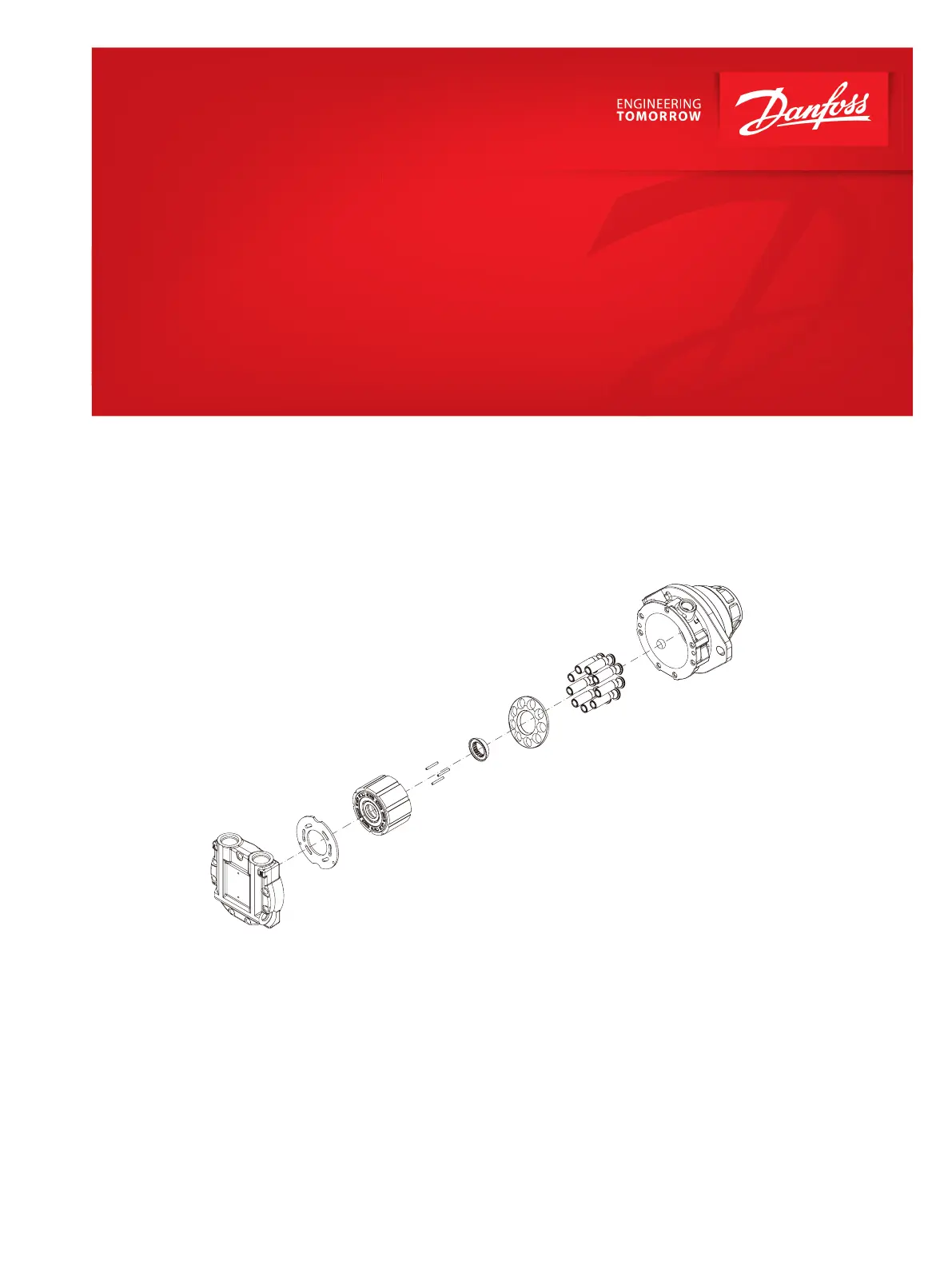
Sida 1/31

Technical Information
MP1 Axial Piston Motors
Size 20/24, 28/32
www.danfoss.com

General Description
Overview..............................................................................................................................................................................................5
Features................................................................................................................................................................................................5
System Diagram................................................................................................................................................................................6
Schematic Diagram..........................................................................................................................................................................7
Technical Specification
Design Specifications......................................................................................................................................................................8
Technical Data................................................................................................................................................................................... 8
Operating Parameters.....................................................................................................................................................................9
Fluid Specifications..........................................................................................................................................................................9
Operation
Loop Flushing Valve......................................................................................................................................................................10
Anti-Cavitation and Shock Valve..............................................................................................................................................12
Speed and Temperature Sensor...............................................................................................................................................13
Available Sensors......................................................................................................................................................................13
Temperature range..................................................................................................................................................................14
Protection Characteristics......................................................................................................................................................14
Mating Connectors...................................................................................................................................................................14
Speed Sensor 4.5 - 8 V.............................................................................................................................................................14
Speed Sensor 7 - 32 V..............................................................................................................................................................15
Sensor Position..........................................................................................................................................................................16
Output Pulses.............................................................................................................................................................................16
Operating Parameters
Overview........................................................................................................................................................................................... 17
Speed Ratings..................................................................................................................................................................................17
System pressure............................................................................................................................................................................. 17
Case Pressure...................................................................................................................................................................................18
Temperature....................................................................................................................................................................................18
Viscosity.............................................................................................................................................................................................18
System Design and Parameters
Installation........................................................................................................................................................................................19
Filtration............................................................................................................................................................................................19
Reservoir............................................................................................................................................................................................19
Overpressure Protection (Only for open circuit system)................................................................................................. 19
Summing System Pressure Conditions..................................................................................................................................20
Loop Flushing..................................................................................................................................................................................20
Case Pressure / Open Circuit Operation................................................................................................................................ 20
Redundant Braking System Requirement.............................................................................................................................20
Fluid selection.................................................................................................................................................................................20
Case drain......................................................................................................................................................................................... 20
Bearing loads and life................................................................................................................................................................... 21
Shaft torque..................................................................................................................................................................................... 21
Shaft Loads.......................................................................................................................................................................................21
Duty Cycle and Bearing Life....................................................................................................................................................... 22
Hydraulic Equations Helpful for Motor Selection...............................................................................................................22
Determination of Nominal Motor Size................................................................................................................................... 23
Variables.......................................................................................................................................................................................23
Master Model Code
Model Code (B-C-D-E)...................................................................................................................................................................24
Model Code (K)................................................................................................................................................................................26
Model Code (L-M-N)......................................................................................................................................................................27
Features and Options
Shaft Options...................................................................................................................................................................................28
Installation drawings
Output Shafts: Option A (SAE A, B, 13 teeth)....................................................................................................................... 29
Technical Information
MP1 Axial Piston Motors Size 20/24, 28/32
Contents
© Danfoss | March 2023 BC290322888218en-000203 | 3

Schematic Diagram
Closed Circuit
A
B
L2 N
L1
P400620
For a close loop system, the system ports (A and B) connect to the high pressure work lines. The motor
receives pressurized fluid in its inlet port and discharges de-energized fluid through the outlet port.
Either port can act as inlet or outlet; flow is bidirectional. The motor has two case drains (L1 and L2). The
motor may include loop flushing. Loop flushing provides additional cooling and filtration capacity.
Open Circuit
A
B
L2 N
L1
CCW
P400648
An open circuit configuration is also possible for the motor and such a system is shown above. A shock
valve and an anti-cavitation valve is provided to protect the unit from sudden pressure surges as well as
cavitation. The flow path of pressurized fluid is from port A through port B. In this configuration, the
direction of rotation of the motor is counter clockwise as seen from shaft side. Similarly, if the anti-
cavitation and shock valve is oriented in the reverse position, the direction of rotation will be clockwise.
Thus, pressurized fluid flow path is from port B through port A.
Technical Information
MP1 Axial Piston Motors Size 20/24, 28/32
General Description
© Danfoss | March 2023 BC290322888218en-000203 | 7
Produktspecifikationer
Varumärke: | Danfoss |
Kategori: | Motor |
Modell: | MP1 |
Färg på produkten: | Zwart |
Förpackningens vikt: | 910 g |
Snäll: | AV-zender |
Maximal upplösning: | 1920 x 1200 Pixels |
Förvaringstemperatur: | -20 - 70 °C |
Videoingång: | DVI-D |
DVI-ingångsportar: | 1 |
DVI-utgångar: | 1 |
Mått (B x D x H): | 49.78 x 75.69 x 14.98 mm |
Video av: | DVI-D |
Maximal-räckvidd: | 1000 m |
Drifttemperatur (TT): | 0 - 50 °C |
Relativ luftfuktighet i drift (VV): | 5 - 85 procent |
Behöver du hjälp?
Om du behöver hjälp med Danfoss MP1 ställ en fråga nedan och andra användare kommer att svara dig
Motor Danfoss Manualer
25 Augusti 2024
18 Augusti 2024
18 Augusti 2024
Motor Manualer
- Royal Enfield
- Victory
- Texas
- TVS
- CRRCpro
- SMC
- Derbi
- Aprilia
- Suzuki
- Benelli
- Mahindra
- Chang Jiang
- Juki
- Indian
- Moto Guzzi
Nyaste Motor Manualer
1 Mars 2025
22 Februari 2025
18 Februari 2025
17 Februari 2025
16 Februari 2025
16 Februari 2025
15 Februari 2025
14 Februari 2025
8 Februari 2025
8 Februari 2025