DataVideo PTR-15T Bruksanvisning
Läs gratis den bruksanvisning för DataVideo PTR-15T (48 sidor) i kategorin Stativ. Guiden har ansetts hjälpsam av 28 personer och har ett genomsnittsbetyg på 4.0 stjärnor baserat på 4 recensioner. Har du en fråga om DataVideo PTR-15T eller vill du ställa frågor till andra användare av produkten? Ställ en fråga
Sida 1/48
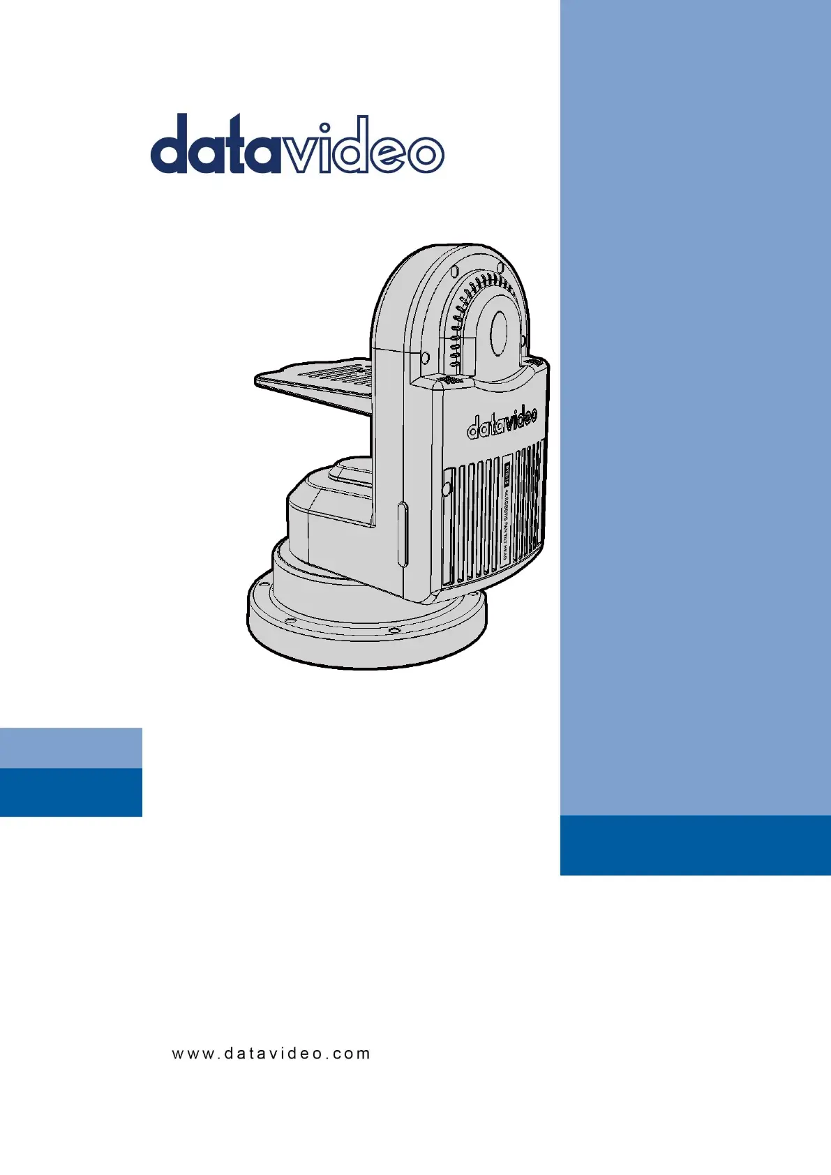
4K HDBaseT ROBOTIC
PTR-15T
PAN TILT HEAD
Instruction Manual
Produktspecifikationer
| Varumärke: | DataVideo |
| Kategori: | Stativ |
| Modell: | PTR-15T |
Behöver du hjälp?
Om du behöver hjälp med DataVideo PTR-15T ställ en fråga nedan och andra användare kommer att svara dig
Stativ DataVideo Manualer

17 Januari 2025
Stativ Manualer
Nyaste Stativ Manualer
4 April 2025
4 April 2025
4 April 2025
4 April 2025
4 April 2025
4 April 2025
3 April 2025
2 April 2025
2 April 2025
2 April 2025