Eliminator Lighting Furious Three RG UV Bruksanvisning
Eliminator Lighting Inte kategoriserad Furious Three RG UV
Läs gratis den bruksanvisning för Eliminator Lighting Furious Three RG UV (26 sidor) i kategorin Inte kategoriserad. Guiden har ansetts hjälpsam av 35 personer och har ett genomsnittsbetyg på 5.0 stjärnor baserat på 9 recensioner. Har du en fråga om Eliminator Lighting Furious Three RG UV eller vill du ställa frågor till andra användare av produkten? Ställ en fråga
Sida 1/26
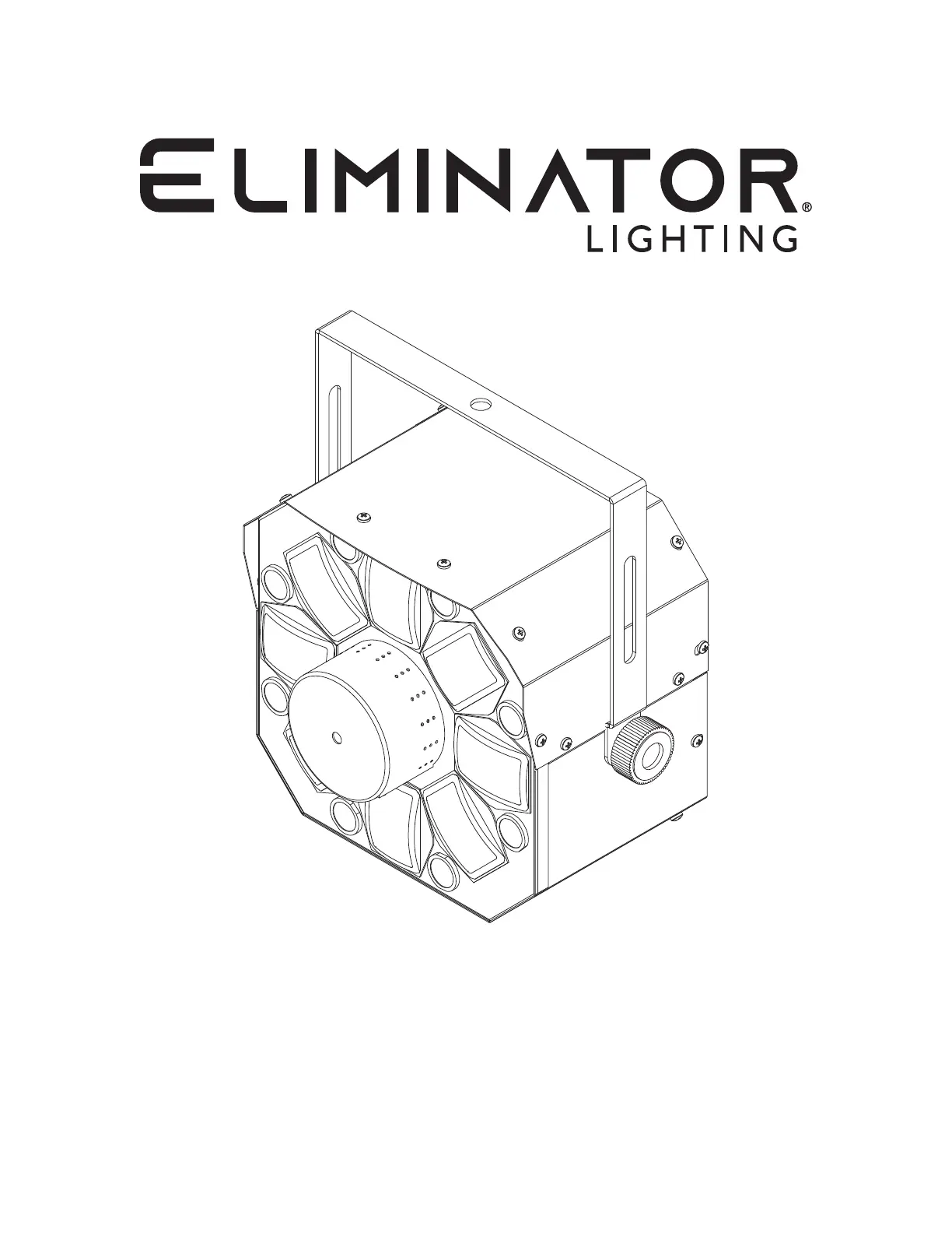
FURIOUS THREE RG UV
User Manual
Produktspecifikationer
| Varumärke: | Eliminator Lighting |
| Kategori: | Inte kategoriserad |
| Modell: | Furious Three RG UV |
Behöver du hjälp?
Om du behöver hjälp med Eliminator Lighting Furious Three RG UV ställ en fråga nedan och andra användare kommer att svara dig
Inte kategoriserad Eliminator Lighting Manualer

29 December 2024
28 December 2024
24 September 2024
23 September 2024
23 September 2024
23 September 2024
23 September 2024
23 September 2024
23 September 2024
23 September 2024
Inte kategoriserad Manualer
Nyaste Inte kategoriserad Manualer
9 April 2025
9 April 2025
9 April 2025
9 April 2025
9 April 2025
9 April 2025
9 April 2025
9 April 2025
9 April 2025
9 April 2025