Emerson 1F85U-42NP Bruksanvisning

Emerson Termostater 1F85U-42NP

Läs gratis den bruksanvisning för Emerson 1F85U-42NP (12 sidor) i kategorin Termostater. Guiden har ansetts hjälpsam av 21 personer och har ett genomsnittsbetyg på 4.3 stjärnor baserat på 11 recensioner. Har du en fråga om Emerson 1F85U-42NP eller vill du ställa frågor till andra användare av produkten? Ställ en fråga

Sida 1/12
PART NO. 37-7573B-EN
1535
1F85U-42NP (Non-Programmable)
Installation and Operating Instructions
80 Series
TM
Universal Thermostat
Battery Powered or Hardwired with Common
white-rodgers.com
emersonclimate.com
Thermostat Applications
Maximum
Stages
Heat/ Cool
Conventional Gas, Oil, Electric
(mV and 24V), Heat only, Cool only or
Heat/Cool Systems
2/2
Heat Pump (Air Source or Geothermal)
with Aux. Heat
4/2
Thermostat Installation
2-4
Wiring
2
Installer Menu
3-4
Test Equipment
4
Using the Thermostat
5-7
Thermostat Overview
5
User Menu
6
Thermostat Operation
6
Troubleshooting
7-8
Homeowner Help Line
8
INDEX
MERCURY NOTICE: This product does not contain
mercury. However, this product may replace a product
that contains mercury. Mercury and products containing
mercury must not be discarded in household trash.
Refer to www.thermostat-recycle.org for information
on disposing of products containing mercury.
Electrical Rating:
Battery Power ..................................... mV to 30 VAC, NEC Class II, 50/60 Hz
Input-Hardwire .................................... 20 to 30 VAC, NEC Class II, 50/60 Hz
Terminal Load .......................................... 1.5 A per terminal, 2.5A maximum all terminals combined
Setpoint Range ........................................ 45° to 99° F (to 37° C)
Rated Dierentials (@ 6°F/ Hr): Fast Med Slow
Heat (Conventional Gas / Oil / Elect) ..... 0.5°F 0.75°F 1.9°F
Cool (Central Air) ................................. 0.9°F 1.2°F 1.7°F
Heat Pump (Heat and Cool) ................ 0.9°F 1.2°F 1.7°F
Heat Pump Aux. .................................. 0.5°F 0.75°F 1.9°F
Operating Ambient .................................. 32°F to +105°F (0° to +41°C)
Display Temperature Range ....................... 32°F to +99°F (0 to 37°C)
Operating Humidity ................................. 90% non-condensing maximum
Shipping Temperature Range ................... -20°F to + 150°F (-29° to +65°C)
Thermostat Dimensions ........................... 3-3/4” H x 6” W x 1-1/8” D
SPECIFICATIONS
Optional Accessory: Wall Cover-Up Plate F61-2663, 6-3/4” W x 4-1/2” H
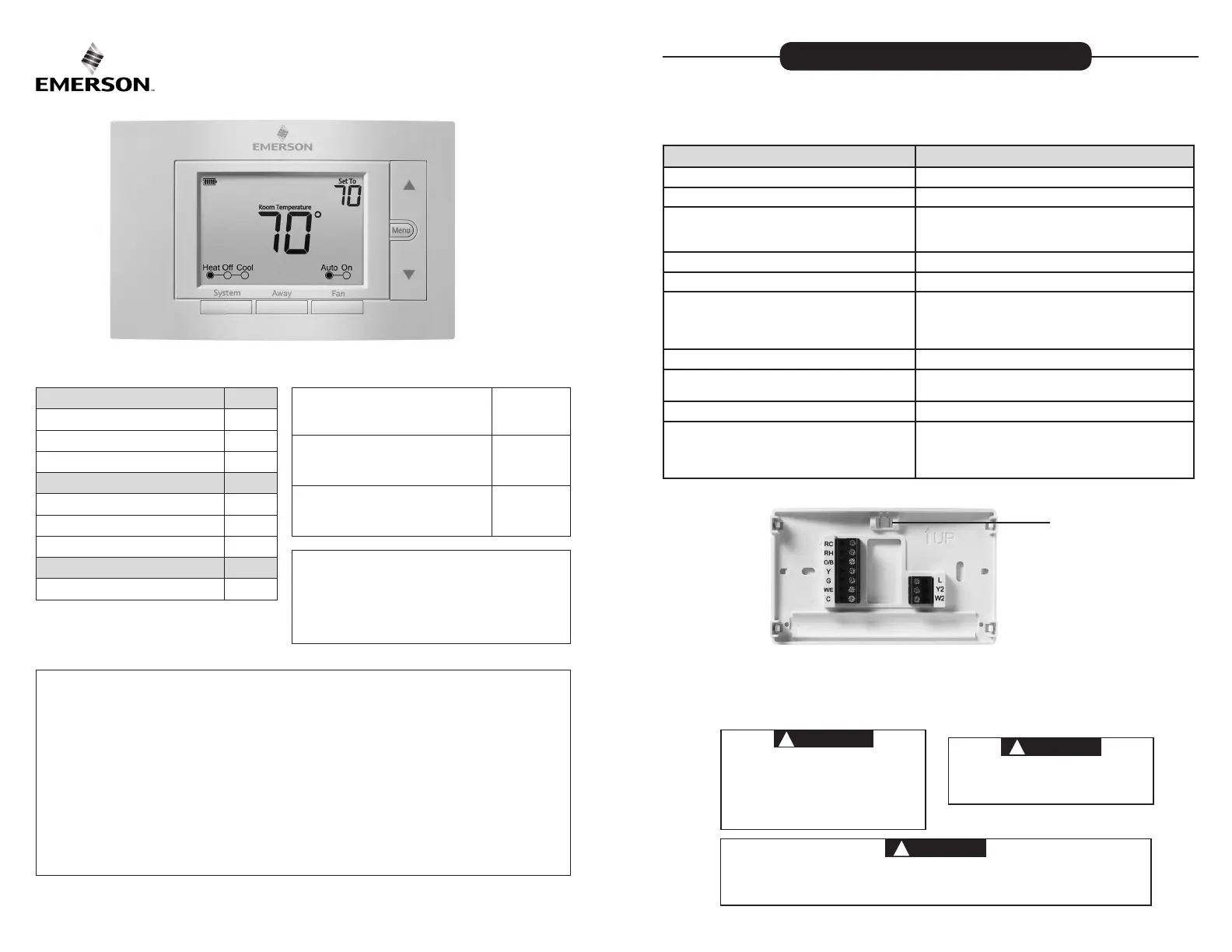
Terminal Designations Terminal Function
RC
Power (24V) - Cooling
RH
Power (24V) - Heating
O/B
6 (not shown) - 3 wire zone valve
Reversing Valve or output for 3 wire zone valves
Congurable as “O” or “B” Reversing Valve or 3 wire
zone heat (power close)
Y
1st Stage Compressor
G Fan Relay
W/E
1st Stage Heat (conventional);
1st Stage Auxiliary Heat (heat pump)
Can operate as Emergency Heat only
(See Installer Menu #15)
C
Common wire for 24V (optional with batteries)
L
Heat Pump Malfunction / Diagnostic terminal
(input signal requires common)
Y2 2nd Stage compressor
W2
2nd Stage Heat (Conventional)
2nd Stage Auxiliary Heat (Heat Pump)
Can operate as 1st Stage Auxiliary Heat
(See Installer Menu #15)
WIRING
Refer to equipment manufacturer’s instructions for specic system wiring information. After wiring, see
INSTALLER MENU for proper thermostat conguration. Wiring table shown are for typical systems and
describe the thermostat terminal functions. Wiring will change when dedicated emergency heat is on
(See Installer menu #15).
THERMOSTAT INSTALLATION
Precautions
Do not exceed the specication ratings.
All wiring must conform to local and national electrical codes and ordinances.
This control is a precision instrument, and should be handled carefully. Rough handing or
distorting components could cause the control to malfunction.
WARNING
!
Do not use on circuits exceeding specied voltage.
Higher voltage will damage control and could
cause shock or re hazard.
Do not short out terminals on gas valve or primary
control to test. Short or incorrect wiring will burn
out thermostat and could cause personal injury
and/or property damage.
CAUTION
!
To prevent electrical shock and/or equipment
damage, disconnect electrical power to system,
at main fuse or circuit breaker box,until
installation is complete.
Leveling Thermostat
Leveling is for appearance only and
will not aect thermostat operation.
CAUTION
!
To prevent compressor and/or property damage, if the outdoor temperature is below 50°F,
DO NOT operate the cooling system.
Do not allow the compressor to run unless the compressor oil heaters have been operational
for 6 hours and the system has not been operational for at least 5 minutes.
2
3
INSTALLER MENU
To prevent changes that may aect system performance, this thermostat has an INSTALLER
MENU and a USER MENU. The INSTALLER MENU provides access to every option, while the
USER MENU provides access to items that will not aect system performance. To access the
INSTALLER MENU press the Menu button for 8 seconds. The display will show item 05 in the
table below. Use Next and Back to navigate through menu items. Press or to change a
menu setting.
Installer Menu #
(Hold Menu 8 Seconds)
Description
Default Setting
(ashing icons)
Settings
(Press or )
05
Outdoor Equipment: selects air
conditioner (AC) or heat pump (HP)
equipment as well as the number of
stage
AC2
AC0
AC1
AC2
HP1
HP2
10
Indoor Equipment: selects whether
the equipment is a gas furnace, elec-
tric furnace or fan only
EL2
FAN
GA1
GA2
EL1
EL2
15
Dedicated Emergency: W/E only
operates in Emergency Aux mode. W2
becomes 1st stage Aux. Heat
OFF
On
OFF
20
O,B or 3 Wire Zone Valve Selection
O
O
B
3
30
Heat Cycle Rate: how often
the heat will turn on
MEd
SLO – slow
MEd – medium
FAS – fast
32
Aux Cycle Rate: how often the
auxiliary heat will turn on
MEd
SLO – slow
MEd – medium
FAS – fast
35
Cool Cycle Rate: how often
the cooling will turn on
MEd
SLO – slow
MEd – medium
FAS – fast
50
Compressor Lockout:
protects the compressor
from short cycling
OFF
On5 minute delay
OFF – no delay
65
Max Heat Limit: maximum set point
for heat mode
99
47 to 99
66
Minimum Cool Limit: minimum set
point for cool mode
45 45 to 97
RC/RH Jumper Wire
This thermostat electrically connects
the RC and RH terminals so a jumper
wire is not required. If the application
provides a separate wire for RC and
RH, clip the RC/RH jumper. This will
isolate both terminals so they can be
independently used.
Baery Locaon
Premium AA alkaline batteries are
required when C-wire is not available.
When C-wire is available, the batteries
provide a back-up source of power
(this will maintain the clock in the
event of a power outage).
4
TEST EQUIPMENT
Turn on power to the system.
Fan Operation
If your system does not have a G terminal connection, skip to Heating System.
1.) Press the fan button to select the On position. The blower should begin to operate.
2.) Press the fan button to select the Auto position. The blower should stop immediately.
Heating System
1.) Press the System button to select the Heat position. Heat Pumps only - if the auxiliary
heating system has a standing pilot, be sure to light it.
2.) Press to adjust thermostat setting to above room temperature. The heating system
should begin to operate and the thermostat will indicate Heat On.
3.) For heat pumps with auxiliary- Press to adjust thermostat setting to 3° above room
temperature. The auxiliary heat should begin to operate and the thermostat will indicate
Heat On Aux.
4.) Press to adjust thermostat setting below room temperature. The heating system
should stop operating and the Heat On icon will disappear.
Auxiliary System ( only for heat pumps with auxiliary)
1.) Press the system button to select the Aux position. This bypasses the heat pump and
runs auxiliary only heat.
2.) Press to adjust thermostat setting to above room temperature. The auxiliary heating
system should begin to operate and the thermostat will indicate Heat On Aux.
3.) Press to adjust thermostat setting below room temperature. The auxiliary heating
system should stop operating and the Heat On Aux icon will disappear.
Cooling System
1.) Press the system button to select the Cool position.
2.) Press to adjust thermostat setting below room temperature. The blower should
come on immediately on high speed, followed by cold air circulation. The thermostat will
indicate Cool On. There can be up to a 5 minute delay. (see INSTALLER MENU, item 50)
3.) Press to adjust thermostat setting to above room temperature. The cooling system
should stop operating and the Cool On icon will disappear.
Installer’s Menu #
(Hold Menu 8 Seconds)
Description
Default Setting
(ashing icons)
Settings
(Press or )
79
Fahrenheit or Celsius °F
°F – Fahrenheit
°C – Celsius
81
Temperature Display Adjustment:
adjust the displayed “Room
Temperature”
0 -5 to +5
83
Continuous Display Light: keep
the backlight always on – “C” wire
required
OFF
On – always on
OFF – momentarily
88
Auto Changeover: thermostat
automatically switches between
heat and cool.
OFF
On – enable auto
OFF – disable auto
99
Keypad Lock: prevent unwanted
changes to the thermostat
OFF
On – disable buttons
OFF – all buttons are active
INSTALLER MENU (C0ntinued)
Note: If Starting Soon is shown on the display, the compressor lockout feature is operating. There will
be up to a 5 minute delay before the compressor turns on (see INSTALLER MENU, item 50).
5
THERMOSTAT OVERVIEW
Before you begin using your thermostat, you should be familiar with its features, display and
the location/operation of the thermostat buttons and switches.
THERMOSTAT BUTTONS
AND SWITCHES
THE DISPLAY
1.) Fan Button 8.) Next (Menu button) is used to navigate within a menu
2.) Away Button (set a frequently used
temperature)
9.) Back (Fan button) is used to navigate within a menu
3.) System Button 10.) Exit (Away button) returns to the home screen
4.) Backlight Button (located on the top
of the thermostat)
11.) Thermostat is protecting the equipment from short cycling
(5-minute delay)
5.) Raises Temperature Setting 12.) Indicates that the system is running in Cool, Heat or Auxiliary
mode. (Heat Pump Only -The auxiliary will run in Heat mode
when the heat pump cannot maintain the set temperature.)
6.) Access Menu Options 13.) SEE TROUBLESHOOTING
7.) Lowers Temperature Setting 14.) Battery status indicator
15.) Replace battery indicator
16.) Temperature setpoint
17.) Appears when the keypad is locked (to prevent unwanted
changes)
USING THE THERMOSTAT
1
2
3
4
5
6
7
8
10
11
12
13
14
15 16
17
9
Replace
appears in the display, new premium brand AA alkaline batteries
should be installed. If the house will be unoccupied for an extended period and either
or “
Replace
” is displayed, install new batteries before leaving.
Whenever
6
USER MENU
To customize thermostat settings, press the Menu button from the home screen. Use the
or buttons to highlight Settings and press Next. Use Next and Back to navigate
through menu items. Press or to change the setting.
User’s Menu #
(Press Menu button
and release)
Description
Default Setting
(ashing icons)
Settings
(Press or )
01
Fahrenheit or Celsius °F
°F – Fahrenheit
°C – Celsius
02
Temperature Display
Adjustment: adjust the Room
Temperature)
0 -5 to +5
03
Continuous Display Light:
keep the backlight always on –
“C” wire required
OFF
On – always on
OFF – momentarily
04
Auto-Changeover: thermostat
automatically switches between
heat and cool
OFF
On - enable auto
OFF - disable auto
05
Keypad Lock: prevent unwant-
ed changes to the thermostat
OFF
On – disable buttons
OFF – all buttons are active
THERMOSTAT OPERATION
Away Stores a frequently used temperature setting so that you can select it with a
touch of the Away button. To set an Away temperature press temp up or temp down
to the temperature you want. At the desired setting, hold the Away button for 3 seconds.
When the setting is stored the set point will ash one time. You can store an Away setting
for both Cool and Heat modes. (Example: Set an Away temperature to 88°F in the summer
for cooling and 55°F in the winter for heating.)
Keypad Lockout To prevent unwanted changes, the buttons can be disabled.
To turn this feature On, press and hold and the Menu button unl the icon appears
(this can also be turned on in the menu). To turn O, press and hold and the Menu
button for 3 seconds.

Produktspecifikationer

Varumärke: Emerson
Kategori: Termostater
Modell: 1F85U-42NP

Behöver du hjälp?

Om du behöver hjälp med Emerson 1F85U-42NP ställ en fråga nedan och andra användare kommer att svara dig