Emko Trans Bruksanvisning
Läs gratis den bruksanvisning för Emko Trans (54 sidor) i kategorin brytare. Guiden har ansetts hjälpsam av 64 personer och har ett genomsnittsbetyg på 4.3 stjärnor baserat på 7 recensioner. Har du en fråga om Emko Trans eller vill du ställa frågor till andra användare av produkten? Ställ en fråga
Sida 1/54
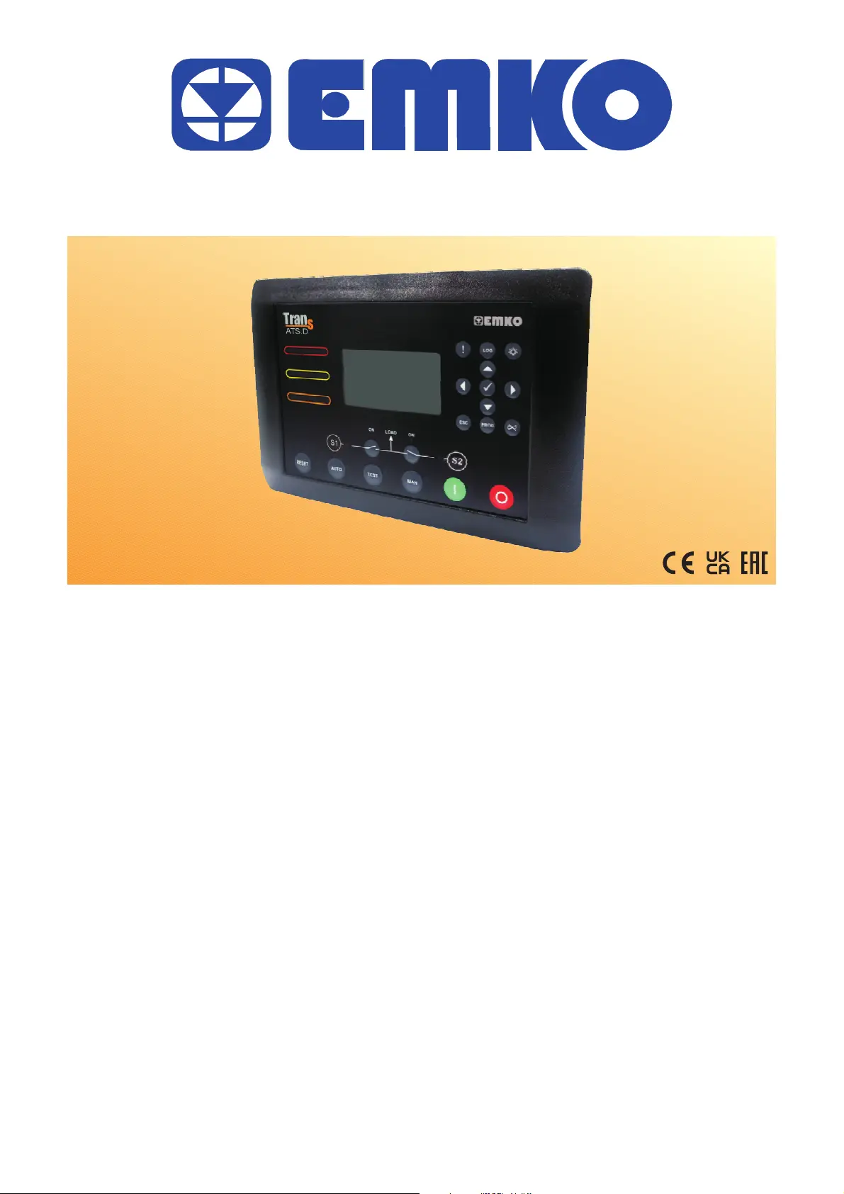
IntroductionManual.ENGTRANS-ATS_D02V0505/23
TRANS-ATS.D
AUTOMATICTRANSFERSWITCH
UserManual
Produktspecifikationer
| Varumärke: | Emko |
| Kategori: | brytare |
| Modell: | Trans |
Behöver du hjälp?
Om du behöver hjälp med Emko Trans ställ en fråga nedan och andra användare kommer att svara dig
brytare Emko Manualer

20 Juni 2025
brytare Manualer
Nyaste brytare Manualer
27 Mars 2026
26 Mars 2026
26 Mars 2026
24 Mars 2026
24 Mars 2026
23 Mars 2026
22 Mars 2026
22 Mars 2026
22 Mars 2026
21 Mars 2026