EverFocus ECOR264-4X1 Bruksanvisning
EverFocus Röstinspelning ECOR264-4X1
Läs gratis den bruksanvisning för EverFocus ECOR264-4X1 (147 sidor) i kategorin Röstinspelning. Guiden har ansetts hjälpsam av 25 personer och har ett genomsnittsbetyg på 4.0 stjärnor baserat på 5 recensioner. Har du en fråga om EverFocus ECOR264-4X1 eller vill du ställa frågor till andra användare av produkten? Ställ en fråga
Sida 1/147
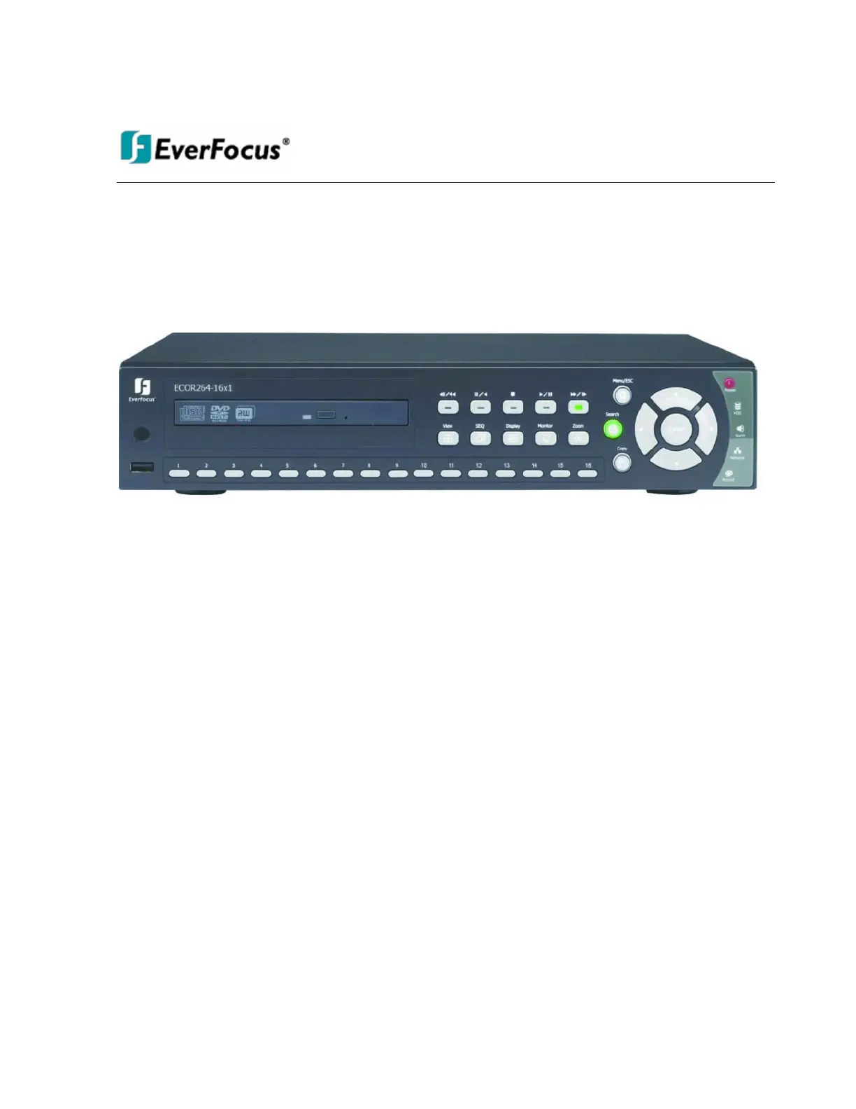
User Manual
E
E
C
C
O
O
R
R
2
2
6
6
4
4
-
-
4
4
X
X
1
1
D
D
V
V
R
R
E
E
C
C
O
O
R
R
2
2
6
6
4
4
-
-
9
9
X
X
1
1
D
D
V
V
R
R
E
E
C
C
O
O
R
R
2
2
6
6
4
4
-
-
1
1
6
6
X
X
1
1
D
D
V
V
R
R
Produktspecifikationer
| Varumärke: | EverFocus |
| Kategori: | Röstinspelning |
| Modell: | ECOR264-4X1 |
Behöver du hjälp?
Om du behöver hjälp med EverFocus ECOR264-4X1 ställ en fråga nedan och andra användare kommer att svara dig
Röstinspelning EverFocus Manualer

9 September 2024
9 September 2024
9 September 2024
9 September 2024
8 September 2024
8 September 2024
7 September 2024
7 September 2024
6 September 2024
5 September 2024
Röstinspelning Manualer
Nyaste Röstinspelning Manualer
5 April 2025
5 April 2025
3 April 2025
5 Mars 2025
16 Februari 2025
25 Januari 2025
31 December 2025
30 December 2025
27 December 2024
22 December 2024